AUSTIN SEVEN ENGINE REBUILD
Article kindly reproduced from the Herefordshire A7 Club.
Part 4 - Main Bearings
Part 1 – The crankcase, camshaft, oil pump, rear main housing.
Part 2 - The cylinder block and connecting rods
Part 3 - Crankshaft & con rods
Part 5 - Carburettors, manifolds, clutch and fan spindle
Part 8 - Attaching the block and cylinder head
Main bearings
Front – There are two different depths of front main bearing housing in two-bearing coil engine crankcases. Until February 1934, the housing was 139/64” deep to accommodate a ball and roller race combination, each 13/16” thick . Thereafter, the housing was reduced to 135/64 to take a pair of slightly narrower angular contact (AC) ball races. I cannot remember the last time I fitted a ball and roller race combination because nowadays, matched pairs of AC bearings are readily available to fit both depths of crankcase housing. The ‘angular contact’ arrangement is far superior, particularly in its axial load carrying ability which is useful in an A7 to resist clutch loads.
New AC bearings are matched
pairs and ours being an imperial size, are not cheap but if I have to buy new,
then I prefer a known make (such as RHP) rather than the slightly less costly
offerings made in China or India. The good news is that pairs of slightly worn
AC bearings can be adjusted so long as the balls and tracks are in good
condition.
It can sometimes be difficult to tell if an existing
bearing is satisfactory for use in a rebuilt engine. Most bearings when
thoroughly cleaned in petrol and dried (compressed air is ideal) will rattle
alarmingly when rotated and can sound decidedly dodgy. However, it must be
remembered that even new ball bearings are designed with some clearance, because
a perfect fit would in theory cause line contact between the balls and the track
and the thing would struggle to rotate (part of the ball surface would have to
slide). A small clearance allows point contact, which enables delightfully
uninhibited rotation. So, if the tracks of a perfectly clean bearing appear
unmarked (no visual damage or corrosion) they can be sparingly lubricated with
very thin oil such as ‘3-in-one’ and rotated slowly whilst applying a variety of
axial and radial loads by hand. If any roughness can be felt it means the balls
and/or track are damaged and the bearing should be discarded. A7 front main
bearings are pretty robust, so, I suspect that any damage is possibly the result
of some muscle-bound ‘mechanic’ fitting or removing them with a large hammer &
drift without first warming the crankcase.
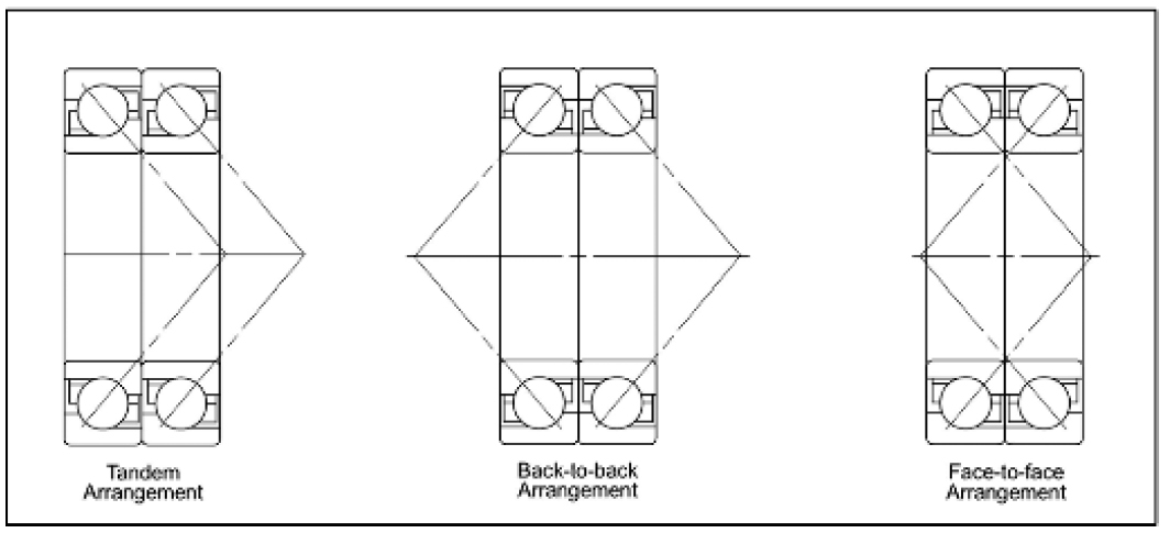
Incidentally, matched pairs of AC bearings can be arranged in three different configurations as shown in the diagram. However, we are concerned only with the ‘back to back’ arrangement which offers good axial and excellent radial load resistance. Just out of interest, ‘face to face’ is less stiff and would let your crankshaft flex even more than usual and ‘tandem’ would be only be appropriate if you needed to resist extraordinary high axial loads - quadruple clutch springs anyone? Anyway, for our ‘back-to-back’ arrangement, the outer race faces that sit together should be marked ‘thrust’ and you will see that they have a deeper shoulder (in a radial sense) supporting the balls at this interface. Similarly, but in reverse, the inner races each have deeper shoulders at the front and back of the combined pair. In theory, we might expect the inner and outer races to be ground so that their faces are exactly in-line when the balls are at design clearance. However, ‘back to back’ matched pairs of AC bearings are manufactured so that the mating surfaces of the outer race each protrude by about a thou’ compared to the inner. So, when the inner and outer races are clamped in position, the bearings attain the correct pre-load between balls and tracks. This pre-load is carefully designed so that the assembly will comfortably accommodate the prevailing combination of radial and axial operating loads, whilst running smoothly and quietly over a good service life.
OK that’s fine for a brand
new AC pair but how do we adjust ours if they are a little slack but otherwise
in good condition? It is useful here to turn-up a couple of simple buttons that
are an easy sliding fit in the bearings with a shoulder to hold the inner races
and a pad so that the whole assembly can be clamped in the vice. Mine are in
aluminium (easy to turn) but almost any material would do and they are shown in
the following photo. Note: the boss on one ‘button’ protrudes sufficiently to
hold the pair in-line. The bearing assembly is held back to back in the vice by
the buttons to ensure the two inner races are pressed firmly together - the
clearance between the outer races is then measured with a feeler gauge.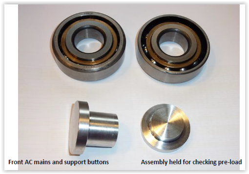
Adjustment is made, either by inserting a (ring) shim of appropriate thickness between the outer races or grinding the mating faces of both inner races. In either case, adjustment should be carried-out only until the slack is just removed but no more. This is easily tested if using a shim, by clamping the bearings in the vice again (with the shim in position) using the two support ‘buttons’ and checking that the outers can just about be rotated relative to one another by hand. If grinding the inner races, they can be checked the same way or with a straight-edge and feeler gauge to ensure each outer race protrudes by about a thou’.
 Incidentally,
A/C bearings can easily be dismantled for cleaning, inspection or grinding, by
driving-out the inner race and it is prudent to employ a cloth to catch the
balls as they fall-out of the cage. Careful examination will tell you the
correct direction to drive the inner race i.e. so that the balls are moved away
from the deeper radial shoulders. If you happen to have a narrow A/C pair
in good condition that you wish to use in an earlier deeper crankcase housing,
you will need to insert a pair of 1/32” shims to the outer races – one each side
of the bearing cluster. This will give the correct 1/64” projection at the front
of the housing to make sure the front clamping plate bears on the outer race to
prevent the whole lot from moving fore and aft. It also ensures the crankshaft
big-end journals correctly line-up with the centres of the cylinder bores.
Incidentally,
A/C bearings can easily be dismantled for cleaning, inspection or grinding, by
driving-out the inner race and it is prudent to employ a cloth to catch the
balls as they fall-out of the cage. Careful examination will tell you the
correct direction to drive the inner race i.e. so that the balls are moved away
from the deeper radial shoulders. If you happen to have a narrow A/C pair
in good condition that you wish to use in an earlier deeper crankcase housing,
you will need to insert a pair of 1/32” shims to the outer races – one each side
of the bearing cluster. This will give the correct 1/64” projection at the front
of the housing to make sure the front clamping plate bears on the outer race to
prevent the whole lot from moving fore and aft. It also ensures the crankshaft
big-end journals correctly line-up with the centres of the cylinder bores.
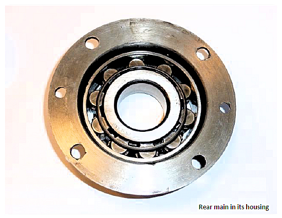
Rear – The rear main bearing is a simple roller affair that handles radial loads well but offers no resistance to crankshaft axial loads and it seems to attract some bad press with frequent accusations of rumble. New ones seem to have just one or two thou clearance but, in my experience, even quite tired ones often don’t have a great deal more. It is widely believed that a beautiful new specimen will quickly wear and then go-on for years so long as the engine oil is frequently changed and the car is in regular use. It seems that rear mains can suffer through condensation and subsequent corrosion of the roller tracks if the car spends long periods standing idle and this might be the source of some unwanted noise.
In a nutshell, if the rear main seems rather loose
but the tracks are not grooved, then you might be able to mix and match a better
combination of parts from your spares box, otherwise a new bearing beckons.
A couple of useful modifications to the rear main bearing housing were mentioned
in Part 1 of these notes. Enlarging the oil return hole (both housing and
crankcase) to decrease the likelihood of it becoming blocked and two cut-outs to
facilitate future outer race removal.
Article kindly reproduced from the Herefordshire A7 Club with many thanks.