AUSTIN SEVEN ENGINE REBUILD
Article kindly reproduced from the Herefordshire A7 Club.
Part 1 – The crankcase, camshaft, oil pump, rear main housing.
Part 2 - The cylinder block, connecting rods and main bearings
Part 3 - Crankshaft & con rods
Part 5 - Carburettors, manifolds, clutch and fan spindle
Part 8 - Attaching the block and cylinder head
There is plenty of available information on dismantling engines that I won’t repeat here (Woodrow is particularly good, also the 750 Club ‘Companion’ pages 107 et seq.) and will therefore assume we are starting with a completely stripped and cleaned set of engine components.
Introduction
Two-bearing A7 coil ignition engines enjoyed three different crankcase
configurations. The first two were for the high frame chassis and had solid
engine mountings. The earliest having its starter motor facing forwards i.e.
alongside the gearbox in the passenger compartment (sometimes confusingly
referred-to as facing backwards) with the starter ring gear on the clutch cover
plate. This was followed by the starter motor facing backwards and located in
the engine compartment. Finally, a flexibly mounted crankcase with bigger feet
was fitted to the low frame chassis cars that retained the backwards facing
starter. The following notes apply to all three versions.
Studs
In order to build a reliable, oil-tight engine, it is first necessary to remove
all studs – i.e. those locating the bellhousing, block and fuel pump. These can
usually be removed by very firmly tightening together, two full steel nuts (not
the ghastly modern countersunk ones) on the protruding thread and lean hard on
the lower nut with a well-fitting ring or combination spanner repeatedly until
it ‘gives’. If this fails, then try applying heat (a hot air gun
works well) to the surrounding aluminium. On the odd occasion this doesn’t work
either, it will necessary to use a stud extractor but this will almost certainly
damage the stud, thus precluding its future use.
It is unlikely that studs will break when being removed from aluminium but not
uncommon when being removed from cast iron. I will discuss the removal of broken
studs in a later Part – ‘The cylinder block’ and head.
Studs should then be cleaned (a rotary wire brush is ideal) and inspected
because only those with perfect threads should be re-used. Damaged studs should
be discarded and replaced.
All threaded stud and bolt holes in mating surfaces should be lightly
countersunk to prevent the aluminium ‘pulling-up’ when tightened, thus
preventing a good seal. Also, all crankcase threads should be gently cleaned
with the appropriate BSW or BSF tap, taking care to remove only dirt/sealant and
not any aluminium. Then, nosepiece, sump, fuel pump and front bearing housing
mating surfaces should be carefully dressed with a file to remove any damage.
Also the bell housing face but this is less critical.
Any damaged threads will need to be repaired. I am not aware of any data that
compare the pull-out strength and costs of the following different methods but I
like to think that my favoured approach might compare well.
The quickest way to repair a damaged thread is undoubtedly the coil insert
process (‘Helicoil’, ‘V-coil’ or similar) – but this requires a specific kit for
each thread type and diameter. Each kit includes an appropriate drill and tap,
together with an insert tool, a number of coil inserts and a tang breaker. The
process is quick and straightforward – the damaged thread is drilled-out, the
new hole tapped and then the coil insert is wound-in maintaining slight downward
pressure and a clockwise motion with the tool provided until it is just below
the mating surface. Finally, the ‘lead tag’ of the coil is broken-off with the
punch and the wire fragment removed. Interestingly, coil repairs are claimed to
be stronger than the original configuration but it is useful to remember that
they can sometimes be less oil-tight than their conventional counterparts.
An alternative approach for repairing threads that take a stud, is to buy (or
make) a stepped stud with a larger thread at one end. The crankcase being
drilled and tapped oversize to suit. A possible extension of this approach would
simply be the deployment of a larger diameter stud. However, this might entail
drilling a larger clearance hole in the mating component which obviously has the
potential to weaken it.
Another approach and the one I usually adopt, is to drill-out and tap the
damaged thread to a size larger than would be used for a stepped stud, then
turn-up a bush that externally matches this newly threaded larger hole and is
threaded internally as per the original. This bush can be made in aluminium but
I prefer to use steel or brass to make it more robust (steel is cheaper but
brass is easier to machine – so, ‘you pays your money and you takes etc etc’).
The bush is secured in position using a high-strength industrial adhesive such
as Loctite 648, then carefully filed exactly flush with the surrounding surface.
This approach takes a little longer but it’s cheap and has never given me any
problems.
Next, the top surface of the crankcase needs to be made perfectly flat if you
want to keep your oil inside the engine. I do this by lapping; starting with
coarse (then finishing with fine) grinding paste mixed with a little diesel or
paraffin. Interestingly, the well-known Chris Gould writes on this very subject
in the October 2018 A7OC magazine and he advocates a totally different approach.
Anyway, whilst lapping, the crankcase should be held firmly in contact with the
plate and moved in a figure of eight motion. This is very important, because
circular or fore/aft movements will tend to leave a high area in the middle. I
use an offcut of granite kitchen work-top about two feet square for lapping but
a sheet of plate glass would also suffice. Some people remove the tappet guides
and lap the crankcase directly to the block but I have always found the
underside of A7 blocks to be reasonably flat. In addition, it can sometimes be
difficult to accurately replace the guides so-that the tappet blocks sit exactly
square to the camshaft. Incidentally, nearly all the A7 crankcases I’ve
worked-on, have had noticeably distorted top surfaces, no-surprise then that so
many engines leak oil between block and crankcase. Some engine builders say that
the top surface of the crankcase is sufficiently flat when a two thou’ feeler
gauge is rejected under a straight-edge. However, I simply continue lapping
until there is an even matt finish over the entire block mating area.
Oil galleries
If modern multi-grade oil is known to have been used in the engine, you
might skip this step. Otherwise, it is essential to thoroughly clean-out all the
galleries before using modern and arguably superior oils. This means removing
the hex’ plugs at each end of the main oil gallery and the one covering the
cross-drilling to the front camshaft bearing. The oil pressure relief valve -
ball, spring and cover plug should be removed together with the two threaded
plugs located at the bottom of the two vertical oil galleries at the back of the
engine. To remove these, it is necessary to clear the screwdriver slots of the
peened aluminium that prevents them from unscrewing in service. This can be
achieved by driving a properly ground screwdriver along the slot in each
direction to clear the peened material, then holding a well-fitting screwdriver
firmly into the slot these plugs will usually unscrew without much trouble.
All the oil passages must be thoroughly cleaned and I use a number of model
traction engine brass wire flue brushes for this purpose (every home should have
these!) together with liberal doses of a petrol/diesel mix. It is amazing how
much crud can usually be extracted.
Front main bearing lip
Sadly, many crankcases have damaged front main bearing lips. Often the result of
the bearings being previously removed by ham-fisted ‘mechanics’ or occasionally
perhaps by poor brakes leading to a frontal impact on the starting handle?
Happily, there is no great load on this front lip in normal service, therefore
some slight damage is acceptable so long as the remainder of the lip is not
cracked. Nevertheless, it is not difficult or expensive to replace a damaged lip
– just a few hours of rather rewarding work – as follows …
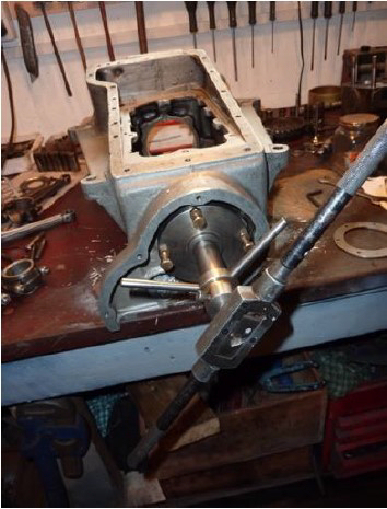
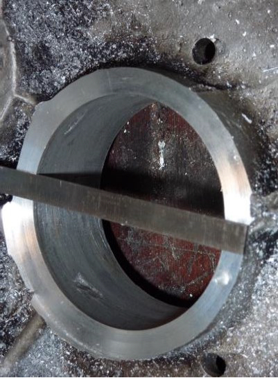
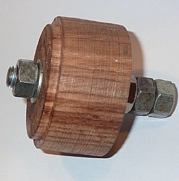
Some years ago I made a very simple device (see photos) to machine-away a damaged aluminium lip. It is hand operated and typically takes about forty minutes of healthy exercise to provide a suitable surface upon which to screw a steel lip replacement ring. Several of our well-known suppliers stock reasonably priced ready cut replacement steel rings but the ones I have seen appear much too thick (at about 5/32”) which in my view are likely to give insufficient clearance to the front of the crankshaft.
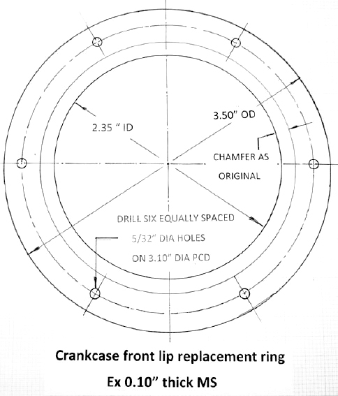
I simply
mark-out and cut a 3.5” diameter. disk from 0.10” thick mild steel to the
dimensions shown in the diagram and initially drill six 2BA tapping holes
equally spaced on a 3.10” PCD. The outer edge (which is not critical, unless you
plan to show photos to your friends!) is roughly sawn then filed almost to size
and the inner hole created by drilling a row of holes in increasing sizes –
inside the marked line to remove the inner portion, which is then filed close to
the finished circle dimension. I then trim the inner and outer edges in the
lathe, exactly to size and create a slight chamfer on the inside that exactly
replicates the geometry of the original Austin flange. If you get stuck-in, this
will take less than an hour and is quite satisfying.
To secure this new plate, some people advocate drilling through from the
front main bearing retaining plate holes and using ¼” diameter countersunk
through bolts. However, once the original flange has been removed, there seems
to be precious little radial width in the remaining aluminium boss and even less
surrounding the ¼” Dia clearance holes in the new plate which might weaken it. I
therefore use six 2BA by 5/8” long steel countersunk set-screws put-in with high
strength Loctite. I have done this on several engines and never had any
problems.
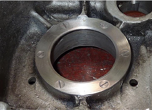
 The
photos show the turned hardwood jig that I use to hold the ring concentric with
the bearing housing whilst drilling for the screws. I rotate the ring on the jig
until none of the six holes correspond with the four front bearing retaining
plate drillings, then drill one hole 2BA tapping (5/32” Dia is OK but a No 24
drill will give much higher engagement ) to a depth of about 1” into the
crankcase. It is also useful to mark the top of the ring, just-in-case the six
holes do not lie on a precise regular hexagon.
The
photos show the turned hardwood jig that I use to hold the ring concentric with
the bearing housing whilst drilling for the screws. I rotate the ring on the jig
until none of the six holes correspond with the four front bearing retaining
plate drillings, then drill one hole 2BA tapping (5/32” Dia is OK but a No 24
drill will give much higher engagement ) to a depth of about 1” into the
crankcase. It is also useful to mark the top of the ring, just-in-case the six
holes do not lie on a precise regular hexagon.
This first hole in the plate is then opened-up to 2 BA clearance (3/16” Dia),
the crankcase hole then tapped 2 BA and a temporary screw tightened
 gently
in position to hold the ring in place whilst still supported by the jig. The
same operation is then repeated for the opposite hole which then holds the ring
exactly in-place before dispensing with the jig and dealing with the four
remaining holes. Finally, the holes in the ring are countersunk to ensure the
screw heads lie perfectly flush when tightened and the ring secured with
high-strength Loctite (e.g. Type 648) on the threads. Job done!
gently
in position to hold the ring in place whilst still supported by the jig. The
same operation is then repeated for the opposite hole which then holds the ring
exactly in-place before dispensing with the jig and dealing with the four
remaining holes. Finally, the holes in the ring are countersunk to ensure the
screw heads lie perfectly flush when tightened and the ring secured with
high-strength Loctite (e.g. Type 648) on the threads. Job done!
Camshaft bearings
The front camshaft bearing is often found to be poorly
located by an ill-fitting original Austin square headed bolt/peg and this can
potentially cause two problems. The first is that the bearing is not held firmly
in position by the peg, so the whole camshaft assembly can move to and fro
longitudinally on the axis of the camshaft as the intermittent valve loads are
applied and relaxed by the helically cut camshaft pinion. This movement can be
the source of an unwelcome rumble from the engine. The second problem is that
oil is likely to leak past the square headed bolt/peg.
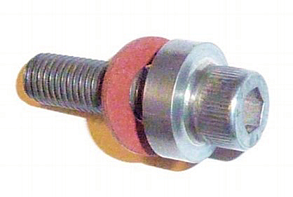
There are numerous articles suggesting how to improve
the location of the front camshaft bearing. Most are based on drilling a tapping
size hole (7 mm dia. is fine) into the bronze bearing exactly on the line of the
former peg then tapping it 5/16” BSF. Finally, turn-up and insert a replacement
screw with a shoulder to seal with a fibre washer against the top surface of the
crankcase. The shoulder on the screw in the photo was silver ‘soldered’ in
position but welding would be OK but not quite so neat – well, my welding
wouldn’t be! Clearly, it is important to check that the new screw reaches
securely into the bearing but not so far as to foul the camshaft journal when
tightened.
The photo shows a locating screw I made from a hexagon
set screw which has the advantage of being accessible for tightening if
necessary, without removing the block - unlike Sir Herbert’s original square
headed offering.
The A7 front and rear camshaft bearings are sometimes
thought to be the source of some undesirable internal oil loss. This is partly
due to the fit of these bearings in the crankcase but perhaps exacerbated by the
generous 5/16” diameter drillings that feed them - the front, horizontally from
the main gallery and the rear vertically above the oil pump.
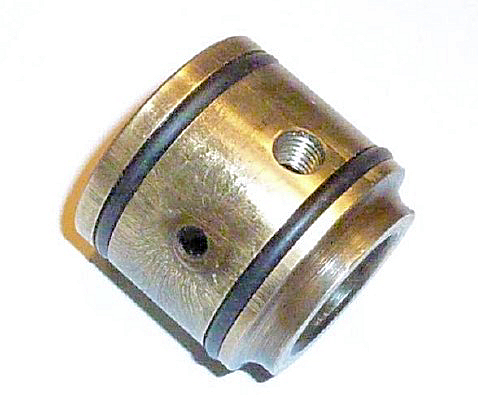
In the interest of preserving as much pressure as
possible for squirting oil towards the all-important
 big
ends, it is quite easy to overcome the above. Firstly, two ‘O’ ring grooves can
be machined on the periphery of the front camshaft bearing each 0.125” wide and
0.107” deep to take 32 mm x 3
big
ends, it is quite easy to overcome the above. Firstly, two ‘O’ ring grooves can
be machined on the periphery of the front camshaft bearing each 0.125” wide and
0.107” deep to take 32 mm x 3
 mm
nitrile rubber ‘O’ rings.
mm
nitrile rubber ‘O’ rings.
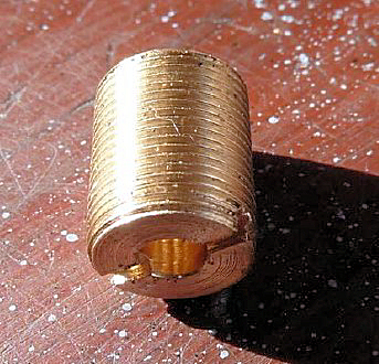
Secondly, the drillings to the front and rear camshaft
bearings can be tapped 1/8” BSPP (0.383” outside diameter x 28 tpi) to an
additional depth of around ¾” and clear of other gallery holes. Then, simple
threaded brass restrictor bushes about 5/8” long & drilled 5/32” dia. are fixed
in position with high strength Loctite.
The centre camshaft bearing lives in a wonderfully
oily environment and is therefore unlikely to be badly worn. However, if there
is any sign of a groove in the outer ring it should be replaced, along with a
set of nine nice new rollers. These items are widely available and reasonably
priced. Special tools are available for extracting & replacing the outer race
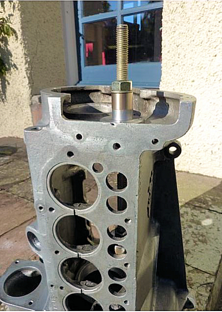
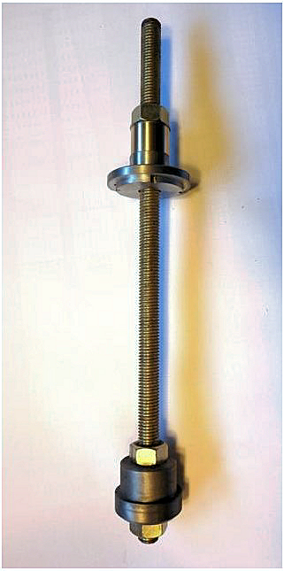
but you can very easily make one yourself – see photos (next page).
This very simple tool comprises a length of 12 mm
studding, a bush that locates in the front cam’ bearing housing and a dolly that
is a sliding fit in the bearing ring to be removed and having a slightly smaller
OD than the ring itself. The crankcase is not terribly strong in this region so
it should be heated locally (a hot air gun is ideal) before commencing. Happily,
the alloy crankcase expands more than the bearing so when the top nut on the
extractor is tightened – the bearing outer ring is easily removed. A similar
procedure is followed to pull the new replacement into position.
Oil pump
In my view, it is a good idea to increase the capacity
of the A7 oil pump because it is a very straightforward modification.
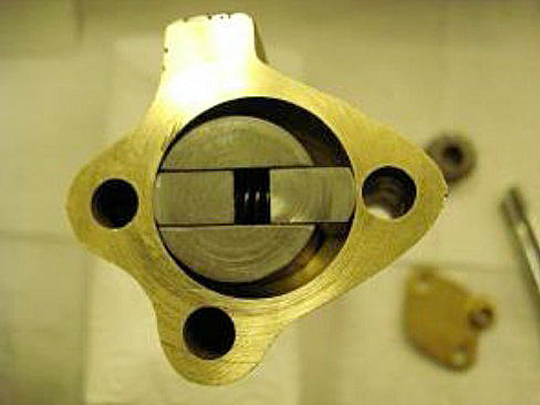
Increased output is achieved by boring the oil pump
body 1/32” oversize on diameter and offsetting the centre of this new bore by
1/64” in the same direction as the original offset. It would be difficult to
make the bore much larger than this due to the proximity of one of the pump
retaining bolt holes (the right hand hole in the photo). This modification is
described on page 254 of the 750 Club ‘A7 Companion’ (6th impression 1990) and
allows the use of standard springs and vanes.
It seems that the standard pump housing bore is 1.000”
diameter perhaps increasing by a few thou’ when worn and I have two over-bored
pumps in my collection that are 20 and 48 thou’ above standard which compare
interestingly with the recommended 31 thou’ (1/32”).
The example shown in the photo, is a pump I bored-out
many years ago that has proved reliable for many thousands of miles and shows no
signs of wear. This is not a difficult job in the lathe so long as you make a
suitable jig to hold the pump body at the correct offset (although it seems that
I may have slightly over-done this) and exactly in-line with the axis of the
lathe. You also need a sharp boring tool to achieve a smooth bore and a sharp
90° corner at the top.
So, what about performance? Well, an often quoted
benchmark for satisfactory oil pressure in a ‘splash feed’ A7 engine is around
1.5 psi per 10 mph in top gear with the engine fully warmed-up. In my
experience, standard pumps often achieve this and both of my higher capacity
pumps manage only a modest increase to around 2.0 psi per 10 mph. Interestingly,
there appears to be precious little difference between the two bored-out pumps
in terms of pressure, despite their difference in bore diameter. Nevertheless,
the A7 oil pump, being a positive displacement configuration, must shift a
greater volume of oil at any given rpm when over-bored. So, even if the gallery
pressure is not much higher than standard, the greater flow can only be a good
thing - sloshing more oil towards the crankshaft and perhaps even helping to
keep the big-ends a little cooler?
Several of our suppliers offer professionally
over-bored (higher capacity) oil pumps for around £60 to £80 and they often come
with new springs, vanes and a decent drive gear.
Oil jets
The oil jets should be inspected and replaced if
damaged. I have come across jets that have obviously encountered flying pieces
of broken crankshaft or suffered at the hands of careless mechanics and these
need to be replaced. However, jets that appear slightly out of shape can often
be gently coaxed back into a serviceable state.
If you decide to replace the jets, they are a press
fit in the crankcase and can be removed by driving them upwards through the main
gallery and out of the jet cover screw aperture. A bespoke drift that fits
around the narrow part of the jet is a really good idea and one can easily be
turned-up.
New jets are available if required from our suppliers
and they are fitted by pressing into position from above after ensuring that
everything is scrupulously clean. A very useful tip before fitting new jets
(thank you Eddie) - is to put a slight countersink in the top (gallery end) that
will help guide a wire down into the jet when attempting to clear a blockage.
Without this, it can sometimes be awkward to coax a wire into the jet.
Flow from oil jet
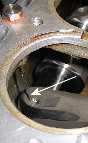
I also believe that it is worthwhile aligning the jets
so that they point more directly towards the lubrication apertures in the
crankshaft as it rotates. However, I appreciate that at least one well known A7
‘expert’ thinks this is unnecessary, believing that the maelstrom of oil mist in
the A7 crankcase with the engine running, is quite sufficient to ensure
satisfactory lubrication of the big ends. He may well be right, especially if
conrod re-metalling and machining leaves a generous end-float on the crankpins
(Woodrow recommends 1/16” which sounds rather a lot to me) – but the fact is,
that many firms only leave two or three thou’. I personally specify six to eight
thou’. It is often surprising how far standard jets need to be moved to achieve
good alignment with the crankshaft troughs and Jack French (who was a strong
advocate of such realignment) reckoned this could be as much as 20°. The method
I use to check and adjust jet alignment is to sit the crankcase in a bath of
diesel with the crankshaft, camshaft and oil pump in place and all gallery plugs
inserted – then drive the top of the oil pump shaft using a rechargeable drill
and a short length of rubber oil hose. It is then easy to see whether the oil
jet reasonably encounters the crankshaft apertures. This process obviously needs
to be repeated with the crankshaft rotated through 180° to check all four crank
troughs and usually - an alignment compromise is necessary. Bending jets to
achieve a satisfactory alignment should be done very carefully. I use a steel
tube with its sharp edges removed that fits loosely over the jet to gently ease
it into the required position. Happily, I haven’t broken or kinked one yet.
It should be noted that if your jets have been
realigned in this way, you will almost certainly need to use a flexible wire
such as bicycle brake cable inner to clear them.
Oil filter
The standard A7 oil filter is simply a wire mesh gauze
mounted over the sump and this is probably quite adequate for intercepting large
lumps of metal and blobs of sealant.
If absolute originality is important, then the rest of
this section is probably of no interest. However, if you wish to almost
completely eliminate the possibility of blocked oil jets, then you might like to
consider fitting an external modern cannister type filter. After all, if you
choose a commercially available kit, it can be fitted and subsequently removed
without making any permanent alterations to your engine.
I personally favour the incorporation of a full flow
filter on an A7 engine. To achieve this I have previously drilled and tapped for
good size, new flow and return fittings into the main gallery but this is a
fairly tricky and time consuming job. My latest engine is fitted with a kit
supplied by Tony Betts (he of no VAT fame) at 7 County Austins (usual disclaimer) which is dead easy to fit but was supplied with what I thought were
rather small diameter take-off and return fittings with an ID of only 5/32” (3.9
mm). Nevertheless, he assures me that many such units are in regular use and
have proved reliable. The take-off simply screws into the threaded hole
originally provided for the oil pressure gauge on the top rear surface of the
crankcase and the return is via an elbow fitting that replaces the ¼ “ BSPP plug
at the front of the main gallery. The filter housing incorporates a new take-off
for the oil pressure gauge and has a mounting arrangement that fits neatly onto
the tops of three head studs.
disclaimer) which is dead easy to fit but was supplied with what I thought were
rather small diameter take-off and return fittings with an ID of only 5/32” (3.9
mm). Nevertheless, he assures me that many such units are in regular use and
have proved reliable. The take-off simply screws into the threaded hole
originally provided for the oil pressure gauge on the top rear surface of the
crankcase and the return is via an elbow fitting that replaces the ¼ “ BSPP plug
at the front of the main gallery. The filter housing incorporates a new take-off
for the oil pressure gauge and has a mounting arrangement that fits neatly onto
the tops of three head studs.
I have heard of people fitting such kits as ‘partial
bypass’ filters but I cannot imagine that much oil would choose to go through
the filter if it can happily and much more easily adopt a direct route straight
to the jets. So, if full flow filtering is to be achieved, it is necessary to
blank-off the main gallery between the oil gauge tapping and the rear-most oil
jet. This is simply achieved by extending the existing ¼” BSPP thread (0.518”
outside diameter and 19 tpi) at the back of the gallery to a total depth of
around two inches and turning-up and fitting a suitable plug. Mine is 5/8” long
and shown in the photo.
When installing the kit, I chose to substitute larger
(¼” ID) steel thin-wall fittings that increased the internal
cross-sectional-area nearly threefold and used larger 3/8” ID flexible oil hose.
Rear main bearing housing
I make two changes to the standard rear main bearing
housing. Firstly, I mill two half round cut-outs in the outer bearing retaining
lip in order to make it easier to remove the outer bearing ring at a later date.
Without these cut-outs this can be rather difficult. Of course, the cut-outs can
just as easily be produced with a rat-tail file.
When it comes to removing the outer bearing ring,
ideally a steel plate ‘drift’ can be made to fit across the ring and snugly into
each cut-out or alternatively, a standard drift can be applied alternately to
each cut-out - not quite so elegant - but it works.
The second change I make, is to enlarge the 3/16” dia.
drilling in the bearing housing and the supporting alloy crankcase to ensure oil
at the back of the bearing can easily return to the sump. I take this to 5/16”
diameter because this passageway was found to be clogged-up on numerous engines
that I have dismantled.
Cleaning & assembly
Finally, the crankcase must be thoroughly cleaned of
all traces of swarf, old oil and particularly grinding paste, paying particular
attention to the oil passage-ways and all internal corners. I do this outside
using a petrol/diesel mix together with high pressure compressed air and this
seems to do the trick.
Degrease, then insert and secure (if fitting an
external oil filter) the new main oil gallery plug also the camshaft drilling
restrictors with high strength Loctite (648 is good). Refit the remaining
Gallery plugs and jet covers with new fibre washers using a very thin film of
‘Blue Hylomar’ or similar sealant.
The two threaded plugs at the lower-end of the
vertical oil ways at the back of the engine should now be thoroughly degreased
and replaced. I use a thin film of high strength Loctite on the threads and
firmly centre-pop the aluminium adjacent to each end of the screwdriver slot as
per original Austin practice.
When replacing the cleaned and checked (or new)
replacement studs, I use a lower strength Loctite (Type 243 for example) to
secure block, fuel pump and bell housing studs.
The oil pressure relief valve can now be reassembled,
and the key point here is that the ball should sit cleanly on its seat. This can
be helped by following model steam engineering practice of placing a hardwood
drift on the ball and giving it a single clout with a medium weight hammer.
Interestingly, a new ball and spring cost very little, so, if you are in any
doubt about either, then it would be sensible to replace them.
Assemble and fit the oil pump, remembering that the
small chamfers on the vanes go at the top, a new paper gasket is required
between pump & crankcase and the skew drive gear must be held securely in
position by the small woodruff key at the top of the drive shaft. Finally,
tighten the securing nut over a new lock washer and fix the spindle cover disc
on its washer with a little sealant in its recess on the top surface.
You now have a truly beautiful bottom-end (if you’ll
pardon the expression!) that is ready for building your pride-and-joy engine and
it should be stored in a completely clean environment, a large polythene bag is
ideal!