SUSPENSION MODIFICATIONS
Following our excellent summary of suspension problems, here are a couple of more advanced modifications described admirably by Terry Griffin of the Midlands A7 Club. Reproduced with many thanks.
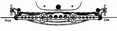
As most people will be aware, Austin Sevens use a transverse front
spring and a pair of swinging shackles to support the front axle. Whilst this is
a simple, effective solution it provides little lateral location as the only
point of locating the axle is the ball joint at the centre of the cross member
2ft back from the front axle. For road-going
cars, this may be fine when pottering through the lanes but as soon as you lower
the spring, drop the radius arms, fit wider wheels and tyres to improve
cornering, the original design is pushed to the limit.
Depending on your spring and shock absorber setup, there are a number of ways to help improve road performance that have been tried and tested on the track. The first and simplest way to stop the ‘lateral rocking’ is to lock one spring shackle in position thus keeping the chassis aligned centrally. This is achieved by making a triangular steel plate to replace one shackle side, fitting a bolt through the upper axle bush and the third corner is fixed to the axle once everything is aligned.
Method two depends on your shock absorber setup and is described by
Reg Nice in the Green Book (Austin Seven Companion) p185. This consists of
fixing one or both ends of the shock absorber arms depending on whether you have
a single, central shock absorber or twin discs with arms. One point Reg does not
emphasis is that the arms need to be horizontal with the pivot points for this
method to be effective. With all the cornering stress transferred through the
radius arms, without an additional location, the nuts need to be really tight,
especially if the arms are dropped. Also the bolt through the radius arm ball-joint
needs to be in good condition and properly adjusted.
The third and probably most important method is to ensure the caster angle (the angle of the swivel pins to the road) which affects the straight ahead stability and the way the car corners, is always a negative or rearward angle (like the head tube on a bicycle) as near vertical swivel pins give very little straight ahead stability and the car needs constant steering corrections (due to linkage play) to maintain a straight line.
Chassis front springs should have 5 degrees of caster built in but most chassis seem to have far less or none at all. Furthermore, unless the chassis sits horizontal to the road the problem can be further exacerbated if the car sits ‘tail high’. A wedge fitted between the front spring and the chassis spring mounting will rectify any lack of caster angle – 4mm (at the thick end of the wedge) will give 6 degrees (minimum setting), and a 6mm tapered wedge will give 8 degrees caster angle. The more the caster angle is increased the more the steering wants to run straight, offset by heavier steering into a corner; so a compromise needs to found to suit your driving style. If a caster wedge is fitted, as with all steering set-ups it is important not to load up the radius arms and shackle pins. In extreme cases it may be necessary to drop the radius arm ball joint or even pack it forward..
Finally, check the steering track as near as possible to 1/8th - 3mm ‘toe in’. With some care and attention Austin Sevens can be made to handle predictably.
part 2 - minimising the A7’s ability to wander
 The
steering box
is connected via the drop arm to the drag link tube, which
has ball joints at each end (both are the same). The front end is fixed to the
steering arm, which bolts through the upper part of the right hand stub axle.
The stub axle pivots on the axle beam via a swivel pin/king pin. Movement is
transmitted to the opposite side through a track rod arm and track rod.
The
steering box
is connected via the drop arm to the drag link tube, which
has ball joints at each end (both are the same). The front end is fixed to the
steering arm, which bolts through the upper part of the right hand stub axle.
The stub axle pivots on the axle beam via a swivel pin/king pin. Movement is
transmitted to the opposite side through a track rod arm and track rod.
Starting
with the steering wheel, it may seem obvious but check for cracks in the spokes,
the rim is secure and the steering wheel nut is tight. Check there is no end
float in the steering column and that the top column bush has no excessive side
to side movement. The column has a worm gear at the bottom end, which engages
with a worm wheel on the shaft (also the drop arm on earlier models). Slack
between these gears translates to movement in the steering wheel. This can be
adjusted out if the wear is not too excessive, but as experienced A7 mechanics
will be aware over-tightening the worm gear will cause both excessive wear and
make the car very stiff to turn on full lock. Vince Leek has made a
modification to the box by adding a roller bearing, which virtually eliminates
the ‘slack tight’ problem.
Often overlooked are the bolts securing the steering box, the three cover nuts and the drop arm nut. At the end of the drag link tube are ball joints. They are secured to the drop arm and steering arm by tapered studs locked in place with castellated nuts and split pins. These ball joints are pre-loaded with a spring under the end cap. If they seem a little soft (but not particularly worn), you can add shims or complete a modification. The modification to the drag link ball joints is made by adding adjusters. Depending on your engineering skills the adjuster can be made in two ways.
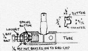
Adjuster brazed to end cap: Drill ¼” hole in the end-cap, braze ¼” BSF nut to the end-c
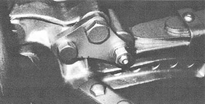
ap to take the adjuster bolt and locknut. Make up the spring button as per the diagram below. Assemble the ball joint with the bolt adjuster screwed out. To adjust, screw in until the pin is locked then back off a quarter of a turn and tighten the lock nut.Alternative method without brazing:
Cut ½” disc from 2mm mild steel, drill a shallow countersink in the centre and then indent with a blunt centre punch. Drill ¼” hole in the centre of the end cap insert nut and locate on BSF bolt flush with nut. Stick button disc on spring with grease, assemble and adjust as above. The finished modification can be seen in the photo below.
Track rod
arm nuts securing the arms to the stub axle can work loose.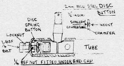 They should be fitted with spring washers and securely tightened. The track rod
ends are fitted with pins and bushes locked with small cotter pins. Any wear in
these means replacement, make sure the steering arms are not twisted as this
causes premature wear in the bushes and pins as does any misalignment in the
track rod. This can be corrected by slackening the clamp bolts on the track rod
ends. Jack up the axle and move the steering from side to side to allow the ends
to realign. If this does not result in free steering then you may have a bent
track rod.
They should be fitted with spring washers and securely tightened. The track rod
ends are fitted with pins and bushes locked with small cotter pins. Any wear in
these means replacement, make sure the steering arms are not twisted as this
causes premature wear in the bushes and pins as does any misalignment in the
track rod. This can be corrected by slackening the clamp bolts on the track rod
ends. Jack up the axle and move the steering from side to side to allow the ends
to realign. If this does not result in free steering then you may have a bent
track rod.
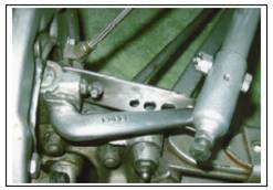
Final checks are king pins and bushes, hub bearing and steering arm. When checking king pins check for any vertical movement as well as side to side rock and make sure the cotter pin is tight. The hub bearings should run smoothly with only a small amount of play. The most important check is the steering arm, check for cracks usually in the corner where it meets the stub axle, new arms are available or if your arm is ok you can fit a brace for additional safety as in the above photo. Many of the tasks this month seem to be mundane and straightforward but well worth spending a little time checking.
Happy motoring.
Terry Griffin
With many thanks
Terry Griffin