3 to 4-speed GEARBOX CONVERSION
On a 1932 RN long wheelbase box saloon without moving the engine forward
By Roger Bateman
(The section dealing with just changing the propshaft and altering the handbrake can be seen separately here)
This is a very common modification and much has
been written about it. The principal reasons for doing it - for me at any rate -
are noise reduction in 1st and 2nd gear, with a
corresponding reduction in wear and tear to the vehicle occupants; and increased
performance to enable me to keep up with other Dorset members’ cars,
particularly on hills! Having just completed this conversion, I have come
to the conclusion that not every model of 3-speed Austin Seven is the same, and
that some of the comments and guidance already written may even be from special
builders who don’t have the same constraints as those of us working on standard
cars. Therefore I have compiled these notes specifically to record how the
conversion was undertaken on Tattybogle, my 1932 RN long wheelbase front-tank
box saloon, retaining the Newton clutch. By all reports, after reading
everything I could find on the subject and talking to the experts, it would seem
to be a straightforward job that could be accomplished one of in two ways. The
4-speed gearbox is a bit longer (3/4”) than the 3 speed, so one can either move
the engine forward (creating fan, exhaust & linkages issues), or shorten the
propshaft. I decided on the latter method as it just seemed easier - especially
as, on page 258 of the green Austin Seven Companion book, the editor says: “I
have always shortened my propshafts rather than shifting the engine forwards;
this obviates some of the snags mentioned”. Then, when an A7 guru suggested to
me that a telescopic Ruby Hardy Spicer prop takes care of the length problem
without the need to cut, weld and balance the original, my decision was
cemented. Whichever way you choose to go, there are usually several issues
to be overcome - notably relating to the floor, the handbrake, the clutch and
the starter.
Floor
Out came the engine and gearbox as a lump and was separated on the bench. Then I offered up the 4-speed box alone (and without the clutch pedal) and found my first problem: not only is the 4-speed box longer but it is also wider. This means that the front of the transmission tunnel has to be flared to accommodate it. After doing this, I was able to offer up the box again to mark and cut an aperture in the floor for the gearbox filler. The transmission tunnel cover with the slot for the handbrake must be modified to suit the newly-flared tunnel, and curved up at the front to clear the fatter gearbox. This is best done right at the end of the job, when finally shaping the floor to suit the installed gearbox. The clutch pedal slot in the floor must be lengthened upwards, and opened out wider at the top, to allow the different pedal to go through as the gearbox is finally fitted.
Clutch
Then I turned my attention to the clutch. The
3-speed and 4-speed withdrawal mechanisms are different and, whilst there are
ways of modifying the 3 speed type described in The Companion, I decided that as
my ‘new’ box was complete with the release bearing, the easiest way was to
convert to the complete 4-speed type which is achieved by changing the release
levers for the later type. First I made a clutch plate centring tool
to use when reassembling the clutch into the flywheel. Then I dismantled the
clutch assembly, and in the process of doing this I discovered that two of the
clutch lining rivets had come adrift and needed replacing. Then it was a simple
process to swap over the release levers and reassemble the clutch again, using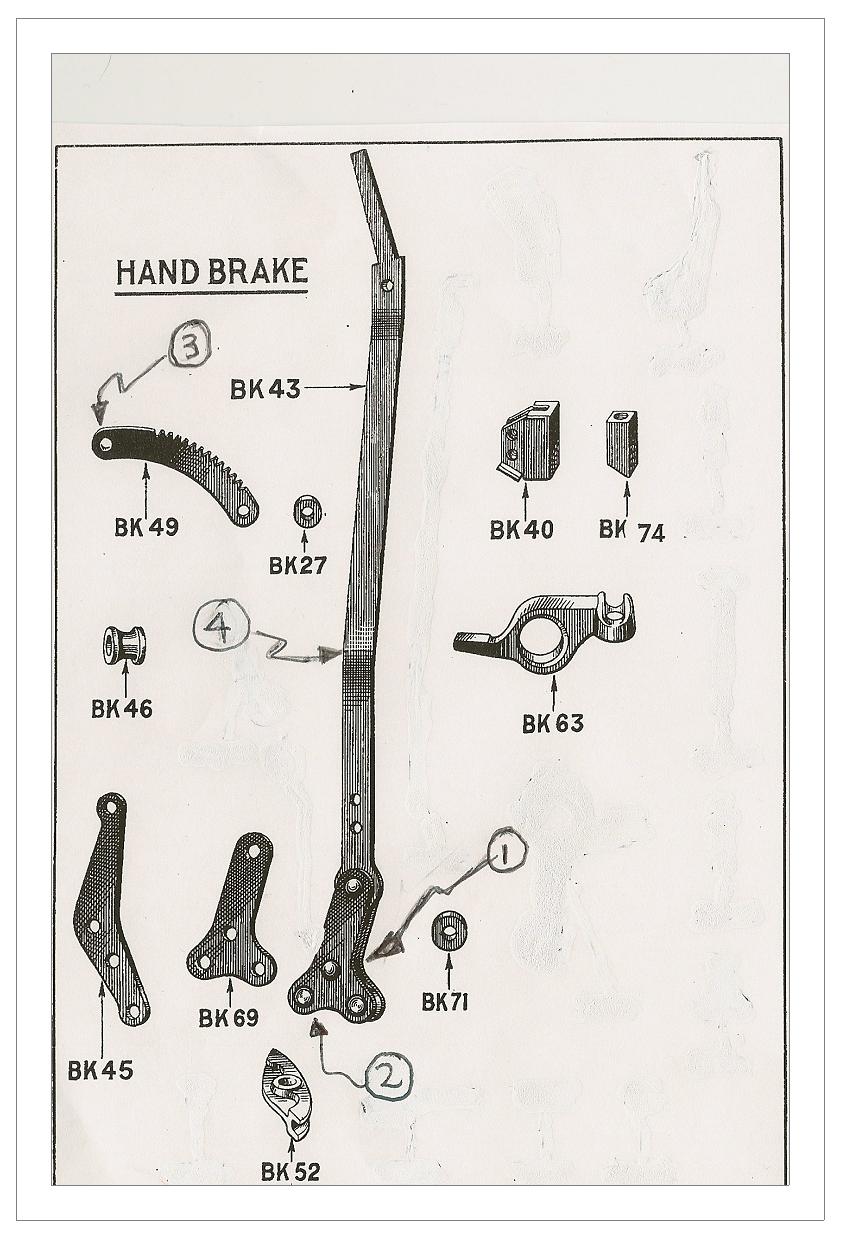 three G-cramps to compress the clutch springs evenly. The 4-speed gearbox input
shaft has a blind spline (why??) so the matching later clutch driven plate must
be used when assembling the clutch back into the flywheel.
three G-cramps to compress the clutch springs evenly. The 4-speed gearbox input
shaft has a blind spline (why??) so the matching later clutch driven plate must
be used when assembling the clutch back into the flywheel.
The Ruby clutch also has ‘mousetrap springs’ fitted to hold the release levers back and stop them flapping about, as they are not in constant contact with the release bearing as per the 3-speed. After investigating what was involved in fitting these, and much discussion with ‘those in the know’, I decided not to bother with this refinement – and so far, so good! At this point the clutch pedal can be fitted - a 4-speed RP-type clutch pedal, one-piece unlike the Ruby (which has clamp, not cotter pin, fitting to shaft), and the gearbox then reunited with the engine.
Next they can be installed into the car. I did this as a lump, as they came out, without giving much thought to the bigger gearbox. The air will become blue at this point, especially if you are doing it on your own, as I usually do - and especially if you have not altered the clutch pedal slot sufficiently. It is a good idea to first remove the accelerator cross shaft from the bulkhead as it gets in the way. Next time I will try installing the gearbox and engine separately into the chassis!
The clutch pedal-to-release bearing clearance must be adjusted – I couldn’t find much on this, but there is very descriptive guidance to be found on the ever-helpful Cornwall Austin Seven Club website at: http:/www.austin7.org/Technical%20Articles/Clutch%20Pedal%20Adjustment/
Propshaft
The prop I had purchased was in good condition and needed no attention, although I had been prepared to overhaul the Hardy Spicers if necessary. So it was offered up and snag no 2 was discovered. Foolish of me, I know, but it was at this late stage that I discovered that the Ruby prop rear flange has 4 holes whereas my original had 6 - and no way would they line up, especially as the location registers are different! So off I went to find a Ruby flange. No problem, thought I, until I discovered that they are like gold-plated hen’s teeth because the Ulster Rep builders have already snaffled them! Everyone I spoke to sucked their teeth and told me the same story. Two members generously offered to lend me one off their spare projects, but then Vince Leek came up trumps and found one in his stash of spares.
Removing the old one proved tricky as it was stuck fast on its taper. The advice in Woodrow’s big red Austin Seven Manual is to strike the rear of the flange axially with a hammer and drift along the line of the woodruff key, but this proved impossible with the axle in the car. I managed it by applying some tension with a 3-legged puller and then a single smart hammer tap to the circumference of the flange, administered radially, did the trick.
So then I could fit up the propshaft on the car. The bolts are larger diameter than on the old prop, and with shaped heads to fit behind the flanges. I overcame this with 8mm x 25 mm bolts with one side of the heads ground flat, and installed with washers and nyloc nuts. OK, it’s as unoriginal as can be, but it works!
Whilst searching for the Ruby torque tube flange, a well-known guru had suggested that I might be able to fit my original prop (type D-2 on page D2 of Woodrow) without shortening it. He wasn’t sure. If so, it would involve using the original fabric coupling mated to an early 4-speed gearbox output star flange (the one from the 3-speed being of no use as it is integral with the output shaft). I did obtain a star flange and offered up the prop to the car to see if this would be possible, but found it was just that bit too long. Perhaps it would fit if the engine/gearbox is unbolted from the chassis and temporarily pulled forward while the prop is fitted, then moving it rearwards again to the normal position afterwards; but I was disinclined to do that as I think the prop would then be solid, without any of the desirable sliding action - which would have, at the very least, a detrimental effect on the fabric coupling. The only way I could envisage that this might work would be to move the engine forwards permanently, which I wanted to avoid.
Handbrake
People said the prop might foul the handbrake - and by golly it does! I read all my books, searched the internet and spoke to everyone I could. I found half a dozen solutions, none of which were extreme enough to solve my ‘little’ problem. Eventually, I worked out a solution that incorporated some of the ideas already suggested by others, plus my own tweaks.
The reference numbers that follow refer to the handbrake drawing.
First, remove the front brake cable centre swivel BK52 by removing the split pin. Then, with an angle grinder, carefully grind the heads off the two rivets holding the handbrake bracket BK45 to the chassis. Remove the handbrake assembly from the car and put the two spacer bobbins BK46 carefully in your spares box as they will no longer be needed. On the bench, grind the head of the rivet (1) flat so it no longer stands proud of the rest of the mechanism. This is the lower of the two rivets joining the plates BK69 to the lever BK43. Fit clevis pin (2) so that the head is on the nearside. Replace bolt (3) at the front of the ratchet rack BK49 with a shallow domed head gutter bolt, head to nearside (you could countersink the hole and use an appropriate c/s bolt if necessary to gain extra clearance).
My handbrake had always had a floppy action and I found two reasons for this: excessive clearance (a) between the lever BK43 and the two ratchet plates BK49, and (b) between the mounting bracket BK45 and the two plates BK69. The solution was to squeeze the BK49s and BK69s in a vice till the clearances were reduced to a satisfactory minimum. It is possible that the clevis pin (2) might also be worn and need replacing, but not in my case.
Replace the two handbrake-to-chassis mounting rivets with bolts of the same diameter - using standard nuts instead of the original bobbins BK46 – one nut at the top and two at the bottom, which will make the handbrake assembly lean to the offside and gain valuable clearance from the prop. I also found that the ratchet pawl and its housing (BK74 & BK40), which had not seen the light of day for 81 years, benefited from dunking in Gunk and lubricating with copperslip grease. Bolt the handbrake assembly in place using nuts and lock washers on the inside of the chassis rail, but first hammer the lower bend (4) in the handbrake lever flat as it will otherwise interfere with the driver’s nearside leg. In my case the operating roller BK71 was wide enough to maintain contact with the adjusting lever BK63 after these mods but, if you find that yours isn’t, try replacing it with an HT bolt and nut of the necessary dimensions.
I found that these mods provided sufficient clearance – just a few thou, but the propshaft does rotate cleanly. However the angle at which the handbrake lever now enters the car means that the slot for it in the transmission tunnel cover must be widened or the cover will no longer fit. I did this by cutting away the outer edge just enough for the fore-and-aft movement of the lever (which is always far less than the length of the ratchet). As this produced an unpleasantly large slot in the floor, I finished it off by riveting in place a strip of inner tube rubber folded double – on the underside - to fully cover the slot to prevent water ingress, which flexes up as the lever passes back and forth along its slot. All is then covered by the carpets.
Oh, and don’t forget to refit the front brake cable and adjust the handbrake!
Speedo Cable
I found that the speedo cable was slightly stretched when connected to the 4-speed box. It could just be fitted, but didn’t work entirely satisfactorily because the square connections didn’t make sufficient contact, so I shall be changing it for a slightly longer one (ideally 19.5”) from one of the specialist parts suppliers.
Starter
The starter motor on the RN sits in the passenger footwell, operated by a button on the floor. However, with the 4-speed box in situ, the starter cannot be refitted in the original position as the gear lever turret is in the way. Hitherto the normal way round this has been to use an earlier ‘bacon slicer’ starter, but this entails cutting the bulkhead as well as changing the original appearance of the interior (and using up a spare part that could be useful for an earlier car). However, the Cornwall Austin Seven club website again comes to the rescue with another solution at: http://www.austin7.org/Technical%20Articles/Gearbox%20Conversion/ This enables the starter to be fitted back in pretty much the original manner, so I have decided to use this method.
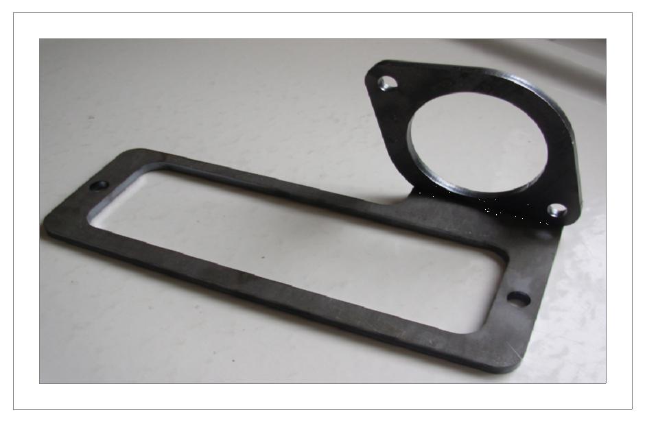
I have had the baseplate and flange laser profile cut from 6mm mild steel plate, which has produced a very clean and accurate job (see photograph). Next they must be welded together after I have established their correct relative positions on the car, but I belatedly find that this has to be done with the engine and gearbox out of the car as there is not enough room in the footwell to accurately position them whilst holding the heavy starter. As I plan to overhaul the engine this winter with a Phoenix crankshaft, I am waiting until then to do this. However, in the meantime, Tattybogle is trundling happily around thanks to the ever-present starting handle and the occupants feet protected from the flywheel by a Ruby tin flywheel cover. In order to get the price down to a reasonable level, I had six sets of plates made, so there will be some available if other members need them.
Of course, you can always use a later crankcase with the starter under the bonnet, but this would alter the original appearance of the interior whilst getting you into an inevitable engine rebuild and most likely other issues too!
On The Road
The drivability of the car is greatly improved - far quieter, nicer gear change and better acceleration and hill climbing, as had been hoped for. This is a conversion well worth doing, unless you are a purist or have a rare model that should not be altered. It was important to me that the conversion should be fully-reversible, and this is so if you keep all the removed parts - except for the cut-outs to the floor, of course! One thing I had to do after the first road test was remove the gear lever and straighten out the bend in the upper few inches, as my hand became painfully intimate with the windscreen opener when 1st or 3rd were selected!
Parts List
4-speed gearbox. Bought sight unseen and condition unknown, so it went to Vince Leek for overhaul and he modified the speedo drive at the same time.
Late type clutch withdrawal fingers.
Late-type clutch driven plate with blind spine.
RP-type clutch pedal (one-piece, unlike Ruby, and clamp not cotter pin fitting to shaft).
Ruby Hardy Spicer prop shaft.
Ruby-type torque tube flange (also called ‘propeller shaft flange’ in the official Austin spare parts list, and ‘pinion shaft flange’ in Woodrow), plus suitable bolts.
Longer speedo cable.
Fabricated starter mounting plate.
Acknowledgements
With particular thanks to: Gary Munn, Vince Leek, Ian Mason-Smith, Bernard Crowley and the Cornwall Austin Seven Club.