The Mechanical Fuel Pump
How It Operates, And How Simple Repairs Can Be Effected
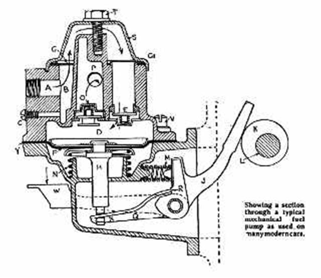
ONE modern method of lifting petrol from the rear tank to the carburetter is by an engine-operated diaphragm pump such as that shown in section in Fig. 1. To be able to effect any necessary adjustments the simple operation of the device should be understood.
The petrol from the tank (drawn up by the action of the diaphragm) enters the pump at A and passes into the annular space B, which acts as a sediment chamber. Any sediment can be drawn off with the petrol by removing the screw C shown just below the inlet. This screw should be very carefully replaced with a copper washer under its head, if there has been any sign of leakage.
Petrol on its way
to the diaphragm chamber D, via the automatic valve E, operated by the downward
stroke of the diaphragm F, passes through a filtering gauze G in an upward
direction and over, in the direction shown by the arrow, to the automatic inlet
valve shown diagrammatically at E. This valve is held up to its seat by a
spring, which allows the valve to open when the diaphragm F descends.
Diaphragm Operation
The diaphragm F is attached to the plunger H which is depressed by the bottom end X of the double lever Q J whose outer end rests against the eccentric K on the camshaft L. The eccentric cannot return the lever, this being accomplished by the spring M. But the diaphragm is automatically lifted by the spring N below it. This spring, raising diaphragm F sends the petrol through the non-return valve O, which rises against the pressure of the spring above it, and the petrol flows past and out at P to the carburetter.
When the carburettor float chamber is filled by the pump, its float cuts off the entrance for petrol by the usual needle valve. This creates a pressure in the pump chamber D and holds the diaphragm F down against the pressure of the spring N. This in turn holds the end X of the lever Q away from the stop R and the pump ceases to operate. The pump remains in this inoperative position until the carburetter level falls and the needle valve opens—until the carburetter requires more fuel, the lever J continuing to be oscillated by the eccentric K.
The Pumping Lever
It must he understood that the lever J is in two pieces. The outer lever J (which contacts with the eccentric) operates the inner lever Q by contact at R so that when the carburetter and the pump chamber D are full the end X of the lever is held down and contact is not made at R the top end of the lever J being held in contact with the eccentric by the spring M (which has no effect in moving the diaphragm F). The spring M merely keeps the lever J in contact with the eccentric and prevents noise which would arise if it were
left free.
There is an outside extension lever W which can be used should the carburetter become dry due to petrol evaporation if the car is left for a long time. This can be hand operated and has the effect of moving lever Q up and down, and so pumping petrol through to the carburetter for starting.
Fault Tracing
Should the pump apparently fail to function, or should it function erratically, or with a reduced fuel supply (indicated by reduced engine power at high revs.) the following points should be checked:
The tank may be empty and should be refilled. There may be a leak at the tube union joints: these should be tightened. There may be foreign matter in the tube. If that is suspected undo the union inlet A, and blow into the petrol tank holding the mouth to the tank filler cap. The petrol should come out of the end of time tube. If it does not, disconnect the unions in the pipe to the tank and pass thin copper wire
through the tubes to push out any obstruction. Replace all tubing and tighten all unions. If a tube has been kinked, that section should be replaced. The cover S holds the filter gauze G below a cork ring G1 which makes the joint. See that this is intact, and lies flat on its seat. The cover can be removed by undoing the central screw T. After fitting the cork ring see that the cover beds down flat upon it before tightening screw T. The filter gauze G may be dirty and stopping the petrol: remove it and clean by swishing it about in a small quantity of petrol. It is of the utmost importance to see that the filter gauze and the cork ring G1 lie quite flat before fitting and tightening the cover. There is a fibre washer under the head of screw T: see that this is in place and is in good sound condition
Petrol Leakage
In some cases petrol leaks at the outside edge of the joint Y which holds the two halves of the pump together. There are screws round the flange which hold the two halves together and nip the diaphragm between them. One is seen at V. These should be tightened: tighten them alternatively, but on no account dismantle the pump body by removing the screws.
Petrol sometimes appears round the pump and seems to come from this joint, while it is really creeping round from an inlet or outlet union, or from the top cover joint which holds the gauze, or even from the top screw T.
If the carburetter floods, do not at first suspect the pump. The needle valve may not be seating. Spin this on its seat to see that it is seating fully and thoroughly clean out the carburetter. There may be some speck of foreign matter between the needle and its seat. The suction and delivery valves in the pump should not be interfered with, and the pump should not be dismantled to gain access to these. They are fitted and adjusted by the makers, and a special fixture is required to re-assemble the parts.
Any defect not covered by the above instructions should be dealt with by a service station equipped with the necessary tools and experience for its correct repair.