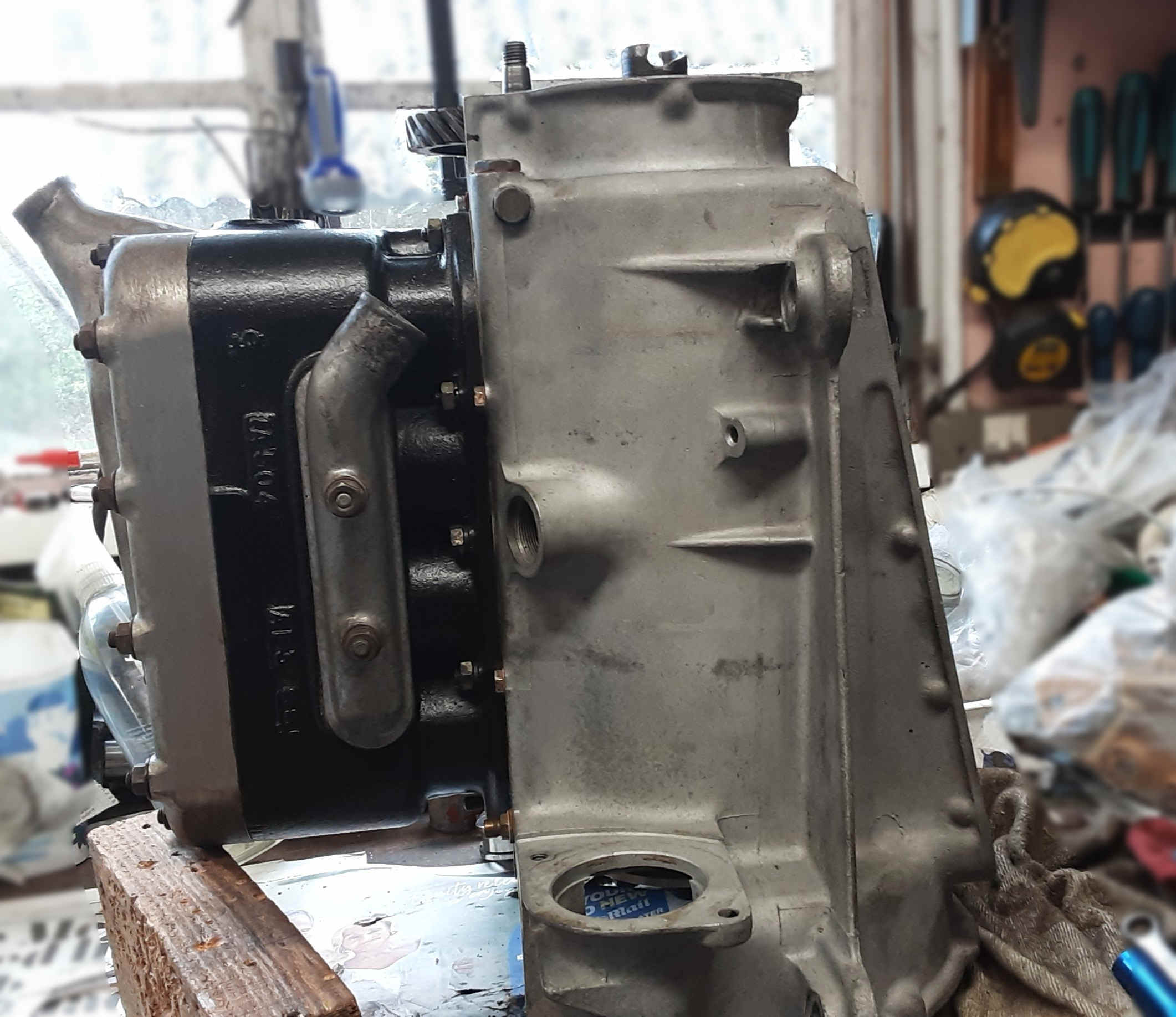
OIL PRESSURE: If you’ve lost oil pressure after a service and have tried all the obvious culprits – pump, drive gear, woodruff key, pressure relief valve and pressure gauge, here’s one you may not think of. There are 2 types of rear camshaft bushes! If you fit the wrong one for your crankcase, you can finish up with no oil pressure. So check the rear bush to ensure it is a good running fit on the camshaft and a close fit within the crankcase avoiding oil by-passing the bush altogether. For 3-bearing engines, check the oil feed pipe to the centre main is seated well and not fractured.
 that the
plug had loosened as part of the settling-down process. But . . . you can
imagine my horror when I found that the thread in the crankcase was very
worn and quickly became non-existent after my attempts to tighten the plug.
The prospect of dismantling the engine passed in front of my horrified eyes
as this thread is (virtually) impossible to get at
with the cylinder block in place, and any swarf that dropped into the oil
gallery would have to be removed. So, after much head scratching,
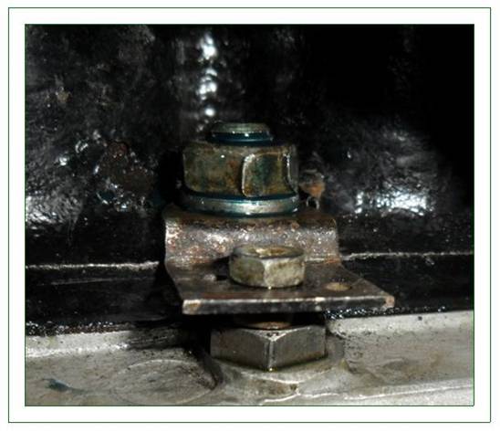
wailing and gnashing of teeth I hit upon the idea of making a small clip that fits under the adjacent cylinder block holding down nut and presses
down on the top of the plug to stop it from being pushed out by oil
pressure. It might leak, but the plug would still be in place. This
was not difficult to make from a piece of flat steel, and I incorporated a
refinement into the basic idea by putting a small set screw and nut in the
outer end and allows adjustment of the force the clip applies to the plug.
In honour of the occasion, I call it The Castleman Clip. I inserted plug into
the crankcase using Loctite 2700 high strength thread locker, fitted the
Castleman Clip under the block bolt and tightened it down. Then I left it
overnight and, next day, started the engine with some trepidation. I need
not have worried! No leaks, engine running normally and oil pressure its
normal lofty self. Roger Bateman
that the
plug had loosened as part of the settling-down process. But . . . you can
imagine my horror when I found that the thread in the crankcase was very
worn and quickly became non-existent after my attempts to tighten the plug.
The prospect of dismantling the engine passed in front of my horrified eyes
as this thread is (virtually) impossible to get at
with the cylinder block in place, and any swarf that dropped into the oil
gallery would have to be removed. So, after much head scratching,
wailing and gnashing of teeth I hit upon the idea of making a small clip that fits under the adjacent cylinder block holding down nut and presses
down on the top of the plug to stop it from being pushed out by oil
pressure. It might leak, but the plug would still be in place. This
was not difficult to make from a piece of flat steel, and I incorporated a
refinement into the basic idea by putting a small set screw and nut in the
outer end and allows adjustment of the force the clip applies to the plug.
In honour of the occasion, I call it The Castleman Clip. I inserted plug into
the crankcase using Loctite 2700 high strength thread locker, fitted the
Castleman Clip under the block bolt and tightened it down. Then I left it
overnight and, next day, started the engine with some trepidation. I need
not have worried! No leaks, engine running normally and oil pressure its
normal lofty self. Roger Bateman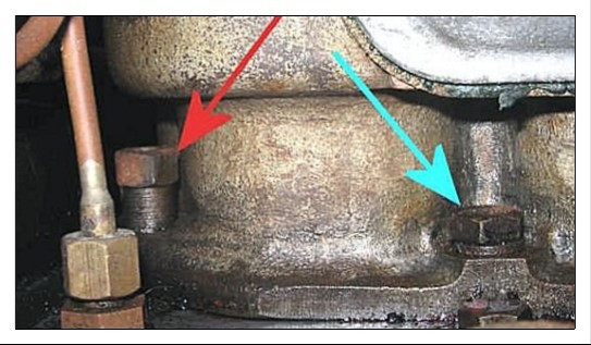 area (OK - I actually bought some more) to take the
top of the nut into an area where there was more room around the nut to get a
1/4" W - 5/16" BS ring spanner on. However, even then I had to thin down the outside of the ring to ensure
it went on OK. The photos show the difference in height.
With thanks to Sandy Croall (Cornwall A7C)
area (OK - I actually bought some more) to take the
top of the nut into an area where there was more room around the nut to get a
1/4" W - 5/16" BS ring spanner on. However, even then I had to thin down the outside of the ring to ensure
it went on OK. The photos show the difference in height.
With thanks to Sandy Croall (Cornwall A7C)CYLINDER HEAD NUTS: Use three or four steel washers under each nut on the A7 cylinder head. With the washers in place, if a thread does strip all you have to do is to remove the washers and use a new nut on the undamaged part of the thread which had been covered by the washers. Presumably the reverse is possible using washers to cover stripped thread so that a nut can be placed higher up the stud on good thread. Bart Walsh Essex A7C
CHECKING COMPRESSIONS:
Here is a simple test if you suspect your engine is low on compression
which will determine if it's your rings or valves, without having to
take the head off.
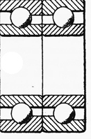
CRANKSHAFT
BEARINGS: The dual-purpose races at the front end of the
crankshaft
 should
be assembled with the faces marked " thrust " towards each other. When
the centre members of the races are tightened on the crankshaft, the
effect should be to hold the outer members together. A method of
testing is to grip the centre members in a vice, when the outer members
or tracks should be free; when wear has occurred, it may be possible to
pass a feeler gauge of .002 in. thickness each side between the outer
members. Should a feeler gauge .003 in. be accepted each side the races
should be renewed. The sketch shows correct fitting.
should
be assembled with the faces marked " thrust " towards each other. When
the centre members of the races are tightened on the crankshaft, the
effect should be to hold the outer members together. A method of
testing is to grip the centre members in a vice, when the outer members
or tracks should be free; when wear has occurred, it may be possible to
pass a feeler gauge of .002 in. thickness each side between the outer
members. Should a feeler gauge .003 in. be accepted each side the races
should be renewed. The sketch shows correct fitting.
MODERN LIP SEALS:
fitting one of the modern lip seals with matching cover plate, available
from our usual suppliers, it will be noticed that comparing the new
cover with the old, there is no cut-away for the oil return to the
crankcase which, if you look with the cover off, is rear of the rear
main bearing outer at about 5 o’clock. Carefully mark the new cover
plate and file or grind the ridge on the plate to align with the oil
hole in the case - this will encourage return of the oil to the sump
when fitted. We always retain the oil dish thrower (outer dish towards
you). Do not over-paste the cover with sealant or the goo can creep and
block the oil return hole which, of course, you have previously ensured
is clear. Try the seal on the flywheel boss before fitting to ensure you
have the correct one and the boss is smooth. Apply a tad of grease where
the lip will seal. Gary Munn “Munwellyns”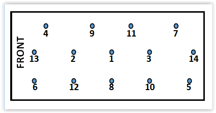
CYLINDER HEAD NUTS: When nuts are tightened down,
the threads on both the stud and nut are stretched a little and it is
good practice to replace each nut not only on the same stud but also the
right way up. (Ideally, one should always use new nuts but ….).
Solution: drive 11/2“ nails 1/2
inch into a block of wood in the correct
pattern of the head studs and when removing the cylinder head pop each
nut and its washer on its correct nail and the right way up. As a bonus,
write the number of order of tightening the nuts with an indelible pen
beside each nail and the word “FRONT” just to be certain.
David Whetton DA7C (with apologies if every other owner wh has
already done this).
.jpg)
FITTING EARLY
CAMSHAFT ROLLERS: Having trouble placing the rollers around
the centre
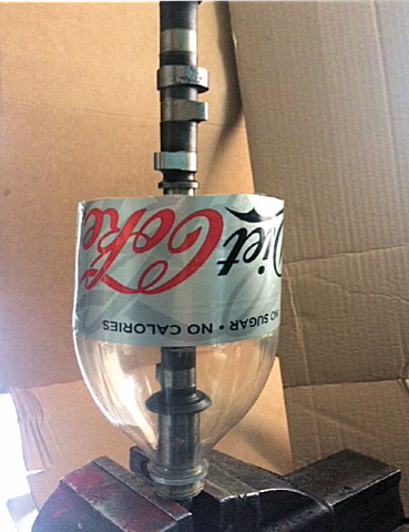 bearing?
Even using grease, how often before getting them all in place one would
drop out and you have to start all over again. The worst part is the one
which drops out falls to the floor, gets covered in dust, and becomes
difficult to find or lost forever. It would be easier if the rollers
didn't end up on the floor. So here is a simple solution. Using a 2.25
ltr plastic drinks bottle, cut to a suitable length, place it round the
camshaft, and mount vertically in the vice. Then if you drop the rollers
they will be caught in the bottle. Vince Leek DA7C
bearing?
Even using grease, how often before getting them all in place one would
drop out and you have to start all over again. The worst part is the one
which drops out falls to the floor, gets covered in dust, and becomes
difficult to find or lost forever. It would be easier if the rollers
didn't end up on the floor. So here is a simple solution. Using a 2.25
ltr plastic drinks bottle, cut to a suitable length, place it round the
camshaft, and mount vertically in the vice. Then if you drop the rollers
they will be caught in the bottle. Vince Leek DA7C
CHEAP PISTON RING
COMPRESSOR: An e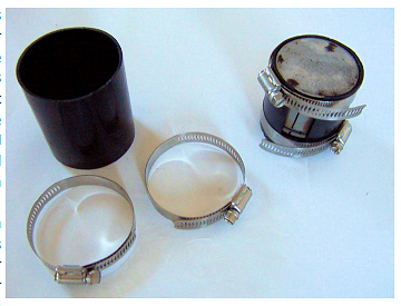 asy
substitute ring compressor can be made up from a short piece of
rainwater pipe, and a couple of hose clips.
asy
substitute ring compressor can be made up from a short piece of
rainwater pipe, and a couple of hose clips.
You need about 3 inches (75mm) of 70mm diameter UPVC rainwater downpipe
and two jubilee clips of a diameter in the 40-80mm diameter range.
Screwfix sell them in 10s, but it may work out cheaper to buy elsewhere
e.g. JIM’s or your friendly local garage.
Now the smallest Austin Seven cylinder bore is 2.20 inches diameter or
2.280 inches diameter absolute maximum oversize. This means you have to
reduce the PVC pipe diameter by cutting it along the length and removing
a strip about 20mm wide. A slit of that width will cover all bore
variants. All that remains to be done is to fit the clamp around the
piston, (using PLENTY OF OIL), tighten up the hose clips and insert the
pistons into the bore in the usual way. Provided you have oiled the
plastic sleeve there is no danger of the rings scraping shavings of UPVC
into the bores. Andy Tewel (Reproduced with permission of the
Cornwall Austin Seven Club).
FITTING CORDS PISTON RINGS: New old stock Cords piston rings are for a Reliant so there are only 3 rings per piston in the set - no scraper ring below the gudgeon pin. The top compression ring supplied has a ridge dodger step. I deglazed the bores before fitting the pistons from the bottom of the cylinder, much easier than from the top as the bottom of the cylinder has a chamfer to help ease the rings into the bore. Some people have reported lack of power after fitting Cords rings, but my car seems fine. I will discover how much the oil consumption has improved after the next run. Roger Ballard DA7C
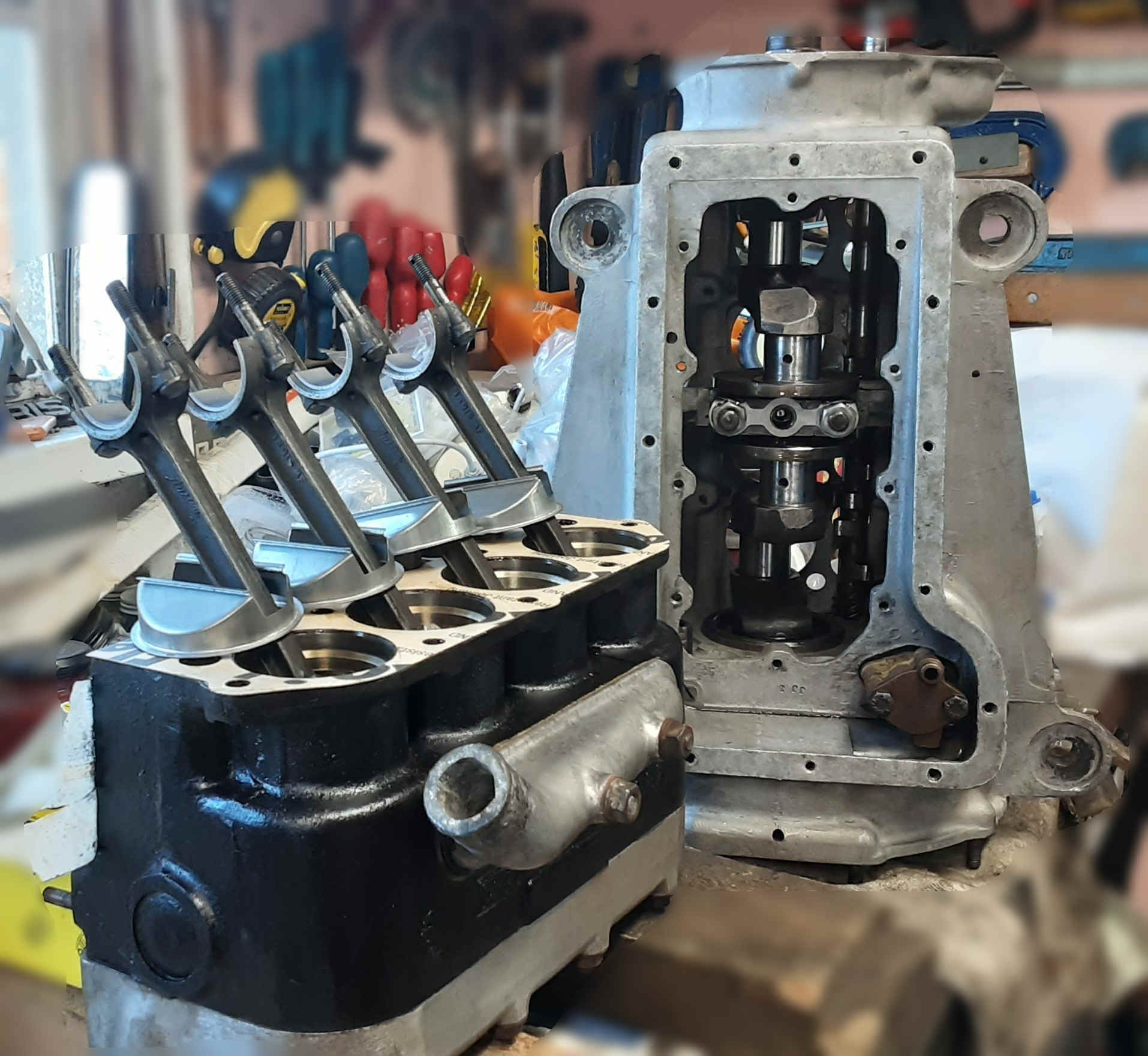
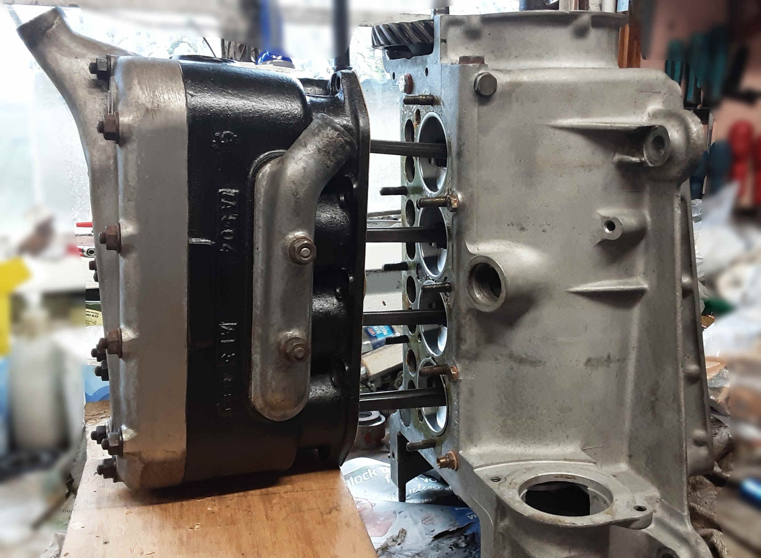
FITTING THE BLOCK: I fitted the rings, pistons, conrods and baffles to the block, then stood the crankcase on the flywheel end, the block is arranged on pieces of wood to lift it level with the crankcase. The units are pushed together until the rod big ends are inside the crankcase then fit the baffles with a dollop of grease. Finally, continue pushing the block and crankcase together and bolt up. Geoff Kingsland DA7C
SKIMMING A HEAD: When I was racing, we always wanted to skim the heads to get the greatest possible compression but, of course, there is a limit because if you take metal from the bottom of the head, the top of the compression chamber comes down nearer the block and, more importantly, nearer to the valves which are popping up and down at a furious rate. One simple way to be sure the tops of the valves aren’t going to hit the inside of the compression chamber is to remove the gasket and then refit the cylinder head, metal to metal as it were. Now, with one hand resting on the top of the cylinder head (and the ignition turned off, of course), pull on the starter cable and you will feel the valves just touching the inside of the head and lifting it up slightly if the head has been skimmed too much. With the head not being ‘nailed down’, the valves are able to just lift the loose head slightly whereas if an over-skimmed head had been fully tightened down, the valves would hit an immovable object and break. The reason for removing the gasket is to give a reasonable margin of error because at three-and-a-half thousand revs, the valves (and the pistons for that matter) leap up higher than their rest level. David Whetton DA7C