Servicing Automatic Ignition Controls
With thanks to Gary Munn, Vince Leek, Ian Mason-Smith, Bernard Crowley and the Cornwall Austin Seven Club.
In order to
keep the engine running at its most efficient, it is necessary to "advance" the
timing
 of
the spark as the engine speed increases, i.e. make the spark occur earlier in
the engine cycle. On pre-Ruby cars this is
achieved by adjusting the manual "IGN" lever at the centre of the steering
wheel. This causes the body of the distributor to rotate in relation to the
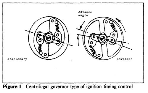
rotor arm inside it. In 1934, with the introduction of the Ruby, the ignition
advance was made automatic by a centrifugal governor contained in the base of
the distributor. The bob weights on the governor cause the cam to rotate
slightly in relation to the shaft which is driving it. So as the engine speed
increases, the cam advances and the spark occurs earlier: as the speed falls,
the bob weights start to return to their normal position in relation to the cam,
thus retarding the ignition. ( See Fig 1). If this mechanism is
inoperative in the static or closed position, the ignition is permanently
retarded which will cause reduced performance, high petrol consumption and a hot-
inning engine. Conversely, should it remain in the fully advanced position,
difficulty in starting may be experienced through back-firing
which may damage the starter drive. Pinking and knocking will also be
experienced upon acceleration and when climbing hills under full throttle
conditions.
of
the spark as the engine speed increases, i.e. make the spark occur earlier in
the engine cycle. On pre-Ruby cars this is
achieved by adjusting the manual "IGN" lever at the centre of the steering
wheel. This causes the body of the distributor to rotate in relation to the
rotor arm inside it. In 1934, with the introduction of the Ruby, the ignition
advance was made automatic by a centrifugal governor contained in the base of
the distributor. The bob weights on the governor cause the cam to rotate
slightly in relation to the shaft which is driving it. So as the engine speed
increases, the cam advances and the spark occurs earlier: as the speed falls,
the bob weights start to return to their normal position in relation to the cam,
thus retarding the ignition. ( See Fig 1). If this mechanism is
inoperative in the static or closed position, the ignition is permanently
retarded which will cause reduced performance, high petrol consumption and a hot-
inning engine. Conversely, should it remain in the fully advanced position,
difficulty in starting may be experienced through back-firing
which may damage the starter drive. Pinking and knocking will also be
experienced upon acceleration and when climbing hills under full throttle
conditions.
Wear in the mechanical parts of the governor is an often unsuspected cause of trouble. Usually the wear in these parts is so gradual that the effect it has upon the performance of the car is not noticed. Wear in the toggles and pivot pins becomes evident after a considerable mileage, while loss of tension in the return springs results in over advancement at certain speeds. Excessive wear between the cam and the spindle results in a varying gap between the contact breaker points which invariably gives rise to misfiring. This is often a source of trouble on cars that have covered a high mileage, and much needless expense is caused by replacing spark plugs, condensers etc, when the real trouble lies in the cam assembly.
The
mechanism consists of two weights, located in position on the revolving drive
plate by pivot pins. The weights are connected to the lower part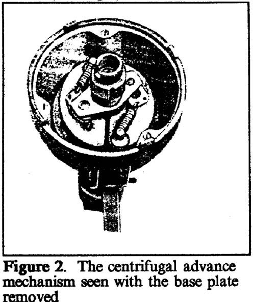 of the cam by toggles and two return springs retain the weights in their closed
or static position. (See Fig 2). As the speed of the drive plate
increases, the two weights pull apart under centrifugal force, overcoming the
tension of the return springs and turning the contact breaker in the direction
of rotation by means of the toggles, thus advancing the spark. With a decrease
in engine speed, the centrifugal force acting on the weights is reduced and the
return springs draw them inwards which in turn draws in the toggles and retards
the spark. When the engine is stationary, the weight are in their closed
position which gives the correct degree of retard for starting purposes. It
should be noted that the cam is not a fixture on the end of the driving spindle
but is free to rotate by movement of the weights.
of the cam by toggles and two return springs retain the weights in their closed
or static position. (See Fig 2). As the speed of the drive plate
increases, the two weights pull apart under centrifugal force, overcoming the
tension of the return springs and turning the contact breaker in the direction
of rotation by means of the toggles, thus advancing the spark. With a decrease
in engine speed, the centrifugal force acting on the weights is reduced and the
return springs draw them inwards which in turn draws in the toggles and retards
the spark. When the engine is stationary, the weight are in their closed
position which gives the correct degree of retard for starting purposes. It
should be noted that the cam is not a fixture on the end of the driving spindle
but is free to rotate by movement of the weights.
Most troubles experienced with the centrifugal advance unit are caused through lack of lubrication. The cam sleeve where it fits over the upper end of the driving spindle is especially susceptible to neglect of this nature, which often results in a complete seizure. The pivot pins and toggles also require periodic lubrication to ensure an easy action and to minimize wear. Lubrication should be made at intervals of 1,000 miles by removing the rotor arm and applying a few drops of engine oil to the hollow end of the cam. The centrifugal advance mechanism should receive similar attention. Whilst lubrication is essential, an excess of oil should be avoided otherwise it may be deposited on the contact breaker points. Avoid the use of vegetable based oils for lubrication purposes.
To check that the cam assembly is properly lubricated, the rotor arm should be pressed in the direction of rotation. It should turn several degrees then return immediately to its static position when the pressure is released. Where the return springs are broken or weakened, the position of the cam may be in the fully advanced position, thus permitting no further forward movement when pressure is applied. To differentiate between this and a stiff or seized cam sleeve, if no forward movement is possible, pressure should be applied m the opposite direction. If the cam freely moves back then the trouble lies with the return springs.
Assuming
that the cam assembly is stiff or tight upon the spindle, a little penetrating
oil should be applied to the hollow end of the cam. After a few minutes the
rotor arm should be replaced and gently worked backwards and forwards until the
action is free and the cam is returned to its static position by the return
springs. The cam can then be lubricated with engine oil. An excessively worn cam
sleeve or spindle results in a sloppy fitting assembly which makes a consistent
gap impossible between the contact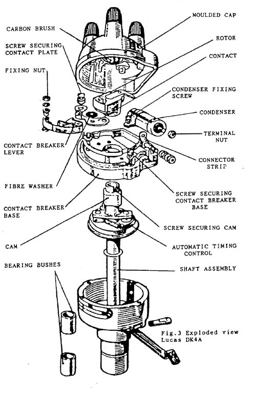 breaker points. While a small degree of play is normal, this should not exceed
.0015". The amount of permissible play is largely determined by the position of
the distributor. Those which are vertically mounted often operate quite
satisfactorily with a degree of play in excess of the figure quoted above.
breaker points. While a small degree of play is normal, this should not exceed
.0015". The amount of permissible play is largely determined by the position of
the distributor. Those which are vertically mounted often operate quite
satisfactorily with a degree of play in excess of the figure quoted above.
To check for excessive wear and play in these parts, turn the engine until the contact breaker points are open. Remove the rotor arm and rock the cam by the fingers towards and away from the fibre heel of the contact breaker assembly. The variation in the gap setting is taken with a feeler gauge and generally this be within the limits stated above. Excessive wear will necessitate replacement of the cam assembly or the driving spindle, or both. Wear in the spindle bush also results in a varying gap.
Where it is necessary to inspect the return springs, toggles and pivot pins, the contact breaker base plate must be removed.
An exploded view of the Lucas DK4 distributor as fitted to the Austin Seven is shown at Fig 3. The advance mechanism is dismantled by removing the screw and washer which secures the cam into position on the spindle, then lifting it clear of the toggles. The toggles are dismantled by removing the return springs and then lifting away. This is followed by the two weights. The pivot pins on the foot of the cam assembly may then be carefully inspected for wear and ridging. The pivot pin holes on the toggles and weights are similarly inspected.
While the mechanism is dismantled it is a good idea to renew the springs which will have lost tension, especially if the car has been in use for any length of time. Care must be taken to obtain the correct replacement springs otherwise the control will be inaccurate. When replacing the springs, they should be retained in the inner small hole of the toggle. Inspection of the toggles will reveal that there are 2 small holes on each toggle, one of which may become blocked and the spring is often fitted to the incorrect hole.
Adapted from an article in the MA7C newsletter with many thanks.