Repairing a PLC Switch
(With
acknowledgements to the wartime issue of "Automobile Electricity" 1940)
The breakdown of a PLC panel
switch
may be due to several
possible
causes, and when
no replacement
is immediately
available, means
must be sought of making a serviceable
repair. It is often possible to
utilise parts
of a replacement of another
type when
they can be inter-changed, but a
close
comparison and inspection to ascertain
the full extent of faults is first necessary.
means
must be sought of making a serviceable
repair. It is often possible to
utilise parts
of a replacement of another
type when
they can be inter-changed, but a
close
comparison and inspection to ascertain
the full extent of faults is first necessary.
External design varies according to type.
One of the commonest types comprises
a cylindrical moulded body
with metal front and rim,
the switch being held in position
by a spring clip with eyeletted ends
secured by a screw and nut.
This encircles the back of the switch
body after the latter has been
fitted in the panel from the front,
and two flat sides of the clip
engage
grooves
in the switch
base so that the clip exerts
pressure to hold the switch
firmly against the
panel (Fig. 1).
In another design, the moulded handle
can be removed from the front when a
slotted ring nut has been unscrewed.
Beneath the handle a larger ring nut
secures the switch in position. Projections on the handle engage slots formed in
the metal rotor sleeve. In each of
these designs the key-operated ignition switch
is concentric with the lighting control
handle.
Where
a regulator box is fitted, the
normal F1 and F2 field terminals
are not used and may be blank studs,
but the D terminal is sometimes used as a junction point to the warning
light. Fig. 2
outlines this type of mounting.
Testing for Defects
With the switch removed from the
panel and wires uncoupled, the nature of
the defect can be ascertained by
simple tests. Bot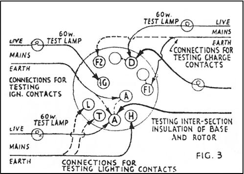 h
ignition key and lighting control
action should be snappy and
decisive. Excessive stiffness or slackness
indicates lack of lubrication
on stud
surfaces or weak springs respectively.
A 12v test lamp
should be used to check insulation
between charging and lighting sections,
the prods being applied to terminals Dand A, between which there should be
no contact in any switch position.
h
ignition key and lighting control
action should be snappy and
decisive. Excessive stiffness or slackness
indicates lack of lubrication
on stud
surfaces or weak springs respectively.
A 12v test lamp
should be used to check insulation
between charging and lighting sections,
the prods being applied to terminals Dand A, between which there should be
no contact in any switch position.
In the case of
a “three-rate” switch, terminals D, F1
and F2
should be all
mutually insulated in "Low" position, D and F1
should
be bridged by
the switch rotor contacts
-
indicated by
test lamp lighting -
in
"High"
and "Side" positions,
and D and F2 should be
similarly
bridged in
"Head"
position. Lighting
combinations
are checked in the same way,
the prods being applied to A and T to light
the lamp in "Side" position, and to A,
T and H in the "Head" position. With
the
ignition switch
on, the centre
terminal A and
1G should be
bridged. Fig.
3
illustrates these tests.
Dismantling
the moulded base from the
rim
plate
assembly
for internal
inspection in
case
of
faulty action
or
bridging,
is
effected
by lifting
the locking
tabs
from
their
slots
and rotating
the rim plate
until
the
three
locating
lugs are opposite the open slots, when
spring pressure will
force rim and
base apart. Care is necessary to avoid loss
of
spring, ignition
key spindle, tube, spring or
rotor.
Fig. 4 shows
the components
in “exploded" order. The moulded base
should first be examined, the following
points receiving special attention.
The three
charging
terminals
form
concave studs inside
the base,
these having two intermediate studs
with no
terminals. It should be noted
that D is
bridged to its right-hand
neighbour
- viewed from inside, as also
is F1.
It will also be seen that terminal A is
internally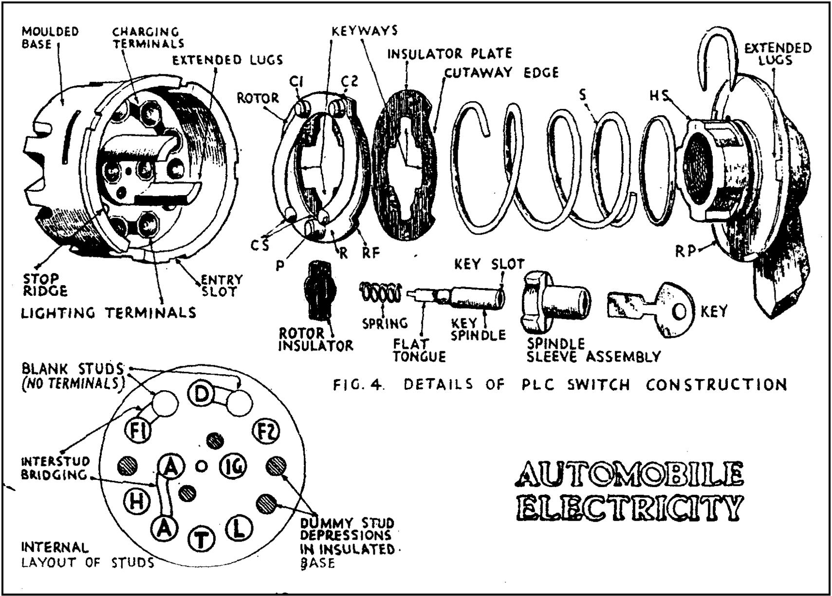 bridged to central A
terminal
ignition
switch stud. These bridging
connections need checking as a break
or bad connection in either of the
charging
bridges
causes
low
output
(Summer
or Low rate only) in "Side" position
when
High
rate
(Winter)
should obtain.
A broken A terminal bridge will
affect ignition feed and any circuit including it, as when ammeter
feed is
connected to central A and auxiliary
or cutout lead is wired to lighting
A. When wiring
up, it is best to connect
all A wires to lighting A, leaving central A
unconnected, when the bridge carries
ignition
current only.
bridged to central A
terminal
ignition
switch stud. These bridging
connections need checking as a break
or bad connection in either of the
charging
bridges
causes
low
output
(Summer
or Low rate only) in "Side" position
when
High
rate
(Winter)
should obtain.
A broken A terminal bridge will
affect ignition feed and any circuit including it, as when ammeter
feed is
connected to central A and auxiliary
or cutout lead is wired to lighting
A. When wiring
up, it is best to connect
all A wires to lighting A, leaving central A
unconnected, when the bridge carries
ignition
current only.
Dummy Contacts
Between the
two groups of studs are
"dummies" - two
concave
indents in the
moulding at
one side. These receive rotor
contact pads in off position, and must be clear of metallic tracking or
dust likely to
cause leakage. The stop
ridge,
controlling the limit of rotor travel
should
be inspected, and the
two extended
lugs which carry
the
ignition
sleeve checked for fracture - a
likely occurrence when the switch has
been strained or forced.
The rotor and insulator
plate.
The lighting section comprises a brass ring
R secured to the insulated
rotor frame
RF,
surmounted
by a C spring with
end
pads
CS
standing
clear
and
embracing a fixed
rivet
stud or pad
P, the three
forming a
group spaced to correspond with stud
positions in the base. Directly opposite
are two other fixed studs C1,
C2, acting as assembly rivets
but insulated by collars from the
brass ring and C spring. They are
spaced two base studs apart and are
bridged together by a strip at the
front of the rotor frame.
Check contacts by applying prods to
the two charging studs C1 and C2, when
the test lamp should light, and check
insulation with prods on C1 and P (no
light). A cut-away sector at the edge
of the rotor frame allows rotation over the stop ridge extending to four
successive stud positions. Four wide "key
ways" in the rotor frame engage keys
on the moulded handle sleeve HS -
allowing end freedom for spring pressure on rotor.
Clean thoroughly and check spring
tension and wear of pads. Insulator
plate IP keeps spring S clear of stud rivets
and bridge strip. The spring is located
on the handle sleeve by a collar and the assembly is held in the rim
plate RP by a circlip engaging a slot.
The switch
illustrated has a flat ignition
key. If a
Yale lock
barrel and
key is fitted
this must be dismantled before
the switch is
opened by taking off the
spindle nuts
and washers located on
spindle end
between ignition terminals,
when the barrel
can be withdrawn complete,
leaving ignition rotor in place.
In the design
sketched the rotor insulator
carries a contact plate located by
lugs engaging
slots, and having two
punched-out
dimples which register
with the two
ignition studs. The
rotor is held
in contact by a compression
spring bearing against a shoulder
on the key spindle.
The flat tongue
at the end of the key
spindle engages
a slot in the rotor
insulator, and
the whole is assembled in
the order
indicated inside the spindle sleeve.
The outer end
of the latter is closed except
for a slot through which the key is
inserted into
the slot at the end of the
spindle. The
key can only enter when
both slots
coincide. Damage to the
sleeve slot is
caused by attempts to
force switch
without proper key.
Faulty Ignition
Faulty ignition
switch
action is
sometimes caused by shearing
of the tongue
slot in the rotor
so that the spindle does
not rotate it
sufficiently. A
new or
replacement rotor
must be
fitted unless the operator
is quick and handy
at
small work, in which case a
steel plate,
slotted to fit the
tongue, and
secured
by
1/16
in.
pins, can be located
between rotor
and spring.
With the
necessary small
tools and
material, the job
can be done in
half an hour.
When
all parts
are
cleaned and wearing surfaces
lightly
coated with
Vaseline, the switch can be assembled.
The spring pads
CS should be urged out to ensure
sound contact, and the stud faces polished
clean. A film of lubricant should be
applied to the handle sleeve keys and a
spot of oil between collar and rim
plate will ensure free action. The ignition
key spindle should be lubricated
before assembly in the sleeve and the tongue must be a smooth easy fit in the
rotor slot. If any of the internal
interstud bridges are doubtful these should be re-soldered.
If there is any difficulty
in
making a neat job on the inside of the
moulding a better way is to solder short
leads to each of the hollow rivet heads
securing the blank stud and to bring
these leads across to the terminals to
which each stud is bridged. The same
can be done in connecting externally
the two A terminals.
Inspection of
the dismantled switch will
make the action
quite clear. In Low or
Summer
position, the three lighting pads, P
and CS,
occupy the studs L and
the two
adjacent dummies, while charging
pads C1 and C2 occupy the left-hand
dummy and the
blank stud bridged to F1. In High position, C1 and C2 connect
F1 and D, while CS and P lie
on T, L and the
lower right-hand dummy.
Side position
brings CS and P on to A, T and
L, while C1 and C2 join the
two blank
studs -
which
are virtual extensions
of F1 and D. Head position causes
H, A and T to
be bridged by CS and P,
while C1 and C2
lie on studs D and
F2. This will
explain the interlocking
combinations
described earlier in this article,
and emphasises the importance of
good insulation
between the charging
pads C1 and
C2, and the lighting pads CS
and P.
Terminal L
(Low) is very seldom
used, being
originally incorporated for
three lamp
lighting sets where head/side
lamps on the wings carried bulbs
with dim and
bright filaments, the
former acting
as side lamps. Terminal
L is alive in
side position only and
cannot be used
for normal side lamp feed as it is dead in Head position.
This terminal
is used on motor cycle
sets where it
feeds the pilot bulb in the
headlamp.
Another application is on cars
having a
separate headlamp switch, wired
from terminal
L, while a pass light is
wired from
terminal H. In this case,
position of
normal "Side" becomes
Sides, Rear
and Headlamp, while position
"Head" becomes
Sides, Rear and Pass
light.
Assembling the Switch
Assembly of
the switch is expedited by
first fixing
the ignition parts in place,
holding these
in by means of a long
screwdriver,
while the main rotor,
insulator
spring and handle sleeve are
got into
position and the bayonet
mounting of the
rim plate secured. The
rotor and
insulator plate should be fitted
with the cutaway
edge
engaging the
stop ridge at limit of the left-hand
rotation while the handle is set to "Low". The keys and keyways will then
engage without
trouble, and the rim
can be rotated
to bring the extended
lugs opposite
entry slots in the base edge.
When a faulty
switch occurs on a vehicle
urgently wanted, a good temporary
substitute comprises a standard
PLC fitted with strap fixing for
mounting on
steering column - like a radio
control dial - short cables being taken from terminals and jointed to wires
removed
from the vehicle switch. The
latter can then be repaired at
leisure, or
replaced, while the vehicle
can be operated
normally with the service
switch. □