OVERHAULING THE STEERING BOX
From an Austin Service Journal
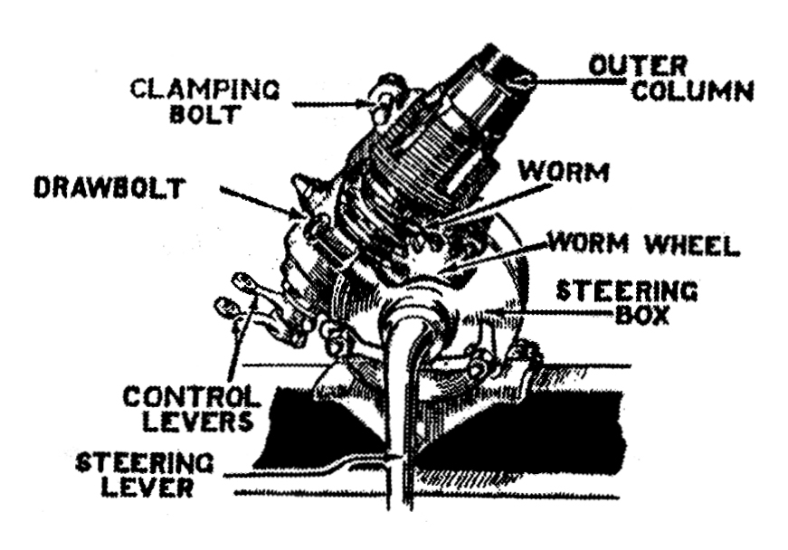
WHEN removing the steering column from the car, the
first. thing to be done, is to remove the small control levers at the base of
the steering box. This done, the horn wire is disconnected from the horn, the
controls and friction disc, at the top of the column, are now removed, by
slackening the clamping pin, which holds the friction disc on to the control
bracket tube and then drawing the disc, controls and the control tubes, out of
the column.
The steering side tube is disconnected from the steering
lever and the steering wheel turned, until the steering arm is in a vertical
position.
The foot brake adjustment is next released in order to remove the brake pedal
fulcrum pin which passes through part of the steering box casting. The thin nut,
on the outside of the fulcrum pin, is removed and the brake pedal is driven off
the pin. The fulcrum pin is removed after undoing the nut on the inside of the
frame channel. The steering wheel and the steering column bracket, which is
under the dash, are now taken off. (On the latest types of Seven, the steering
wheel fits on to a splined section, at the top of the inner steering column and
is held in position by means of a large nut. On older types, it is fastened to
the top of the inner column by means of a clamping bolt). When these have been
removed, the complete steering column may be withdrawn from the front of the
car.
When the column has been removed from the car, it is held in a vice by means of the outer column. The steering box locking washers are knocked back and the holding down bolts are removed. The steering box cover is next taken off, complete with the worm wheel and steering lever. The steering box clamping pin is removed and the set screws taken out. The box is now free to be unscrewed from the base of the column, bringing with it the control bracket tube. When these two components are removed, the steering inner column, with the steering worm and thrust washer, is removed from the outer column. All the components are now thoroughly cleaned and dried.
The worm and worm wheel are now examined for wear.
If the worm is badly worn, a new inner column will have to be fitted complete.
To remove the worm wheel from the steering lever spindle, the lock-washer is
knocked back and the nut which holds the worm wheel on to the taper, is
unscrewed. The wheel is now removed from the spindle by means of a mandrel press
or similar hand press. On no account should any attempt be made to drive out the
spindle with a hammer as, if this is done, one is liable to damage both the
cover and the spindle. A special note should be made at this point of the
keyway which was in use before the worm wheel was removed.
The spindle is now examined for wear in the bush. If any
excess wear is found, the key is removed from the spindle and the spindle itself
pulled out. The felt washer housing, which fits on the outside of the cover, is
removed, bringing the felt washer with it. The worn bush is pressed out and a
new one fitted. This is reamered out to fit the spindle and the felt housing and
felt washer or a new one, if necessary, refitted. It sometimes happens that the
housing is damaged in getting it off. In this case a new one is fitted and is
centre punched in two or three places around its base to hold it in position.
The spindle is now refitted and the key replaced in its keyway.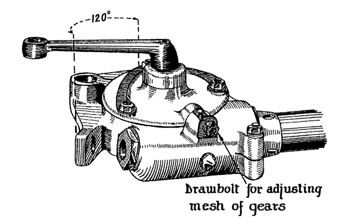
The full travel of the steering arm in service is only 120 degrees, so that only one-third of the teeth on the worm wheel will be worn. It is for this reason that three keyways are cut in the wheel so that it may be refitted to the steering lever spindle using another keyway—thus bringing another set of teeth into mesh with the worm.
Before refitting the worm wheel to the spindle, the taper on the spindle and the taper in the wheel are wiped thoroughly clean. The dropped portion of the steering lever is now held in a vice with the spindle pointing vertically upward. The wheel is fitted on to the taper using another keyway. The lock washer, or a new one if necessary, is fitted with the three tangs fitting into the three keyways in the wheel. The nut is now put on and tightened down until the worm wheel is pushed home on to the taper. The lock washer is then knocked up.
The worm and worm wheel are now smeared with a small quantity of grinding compound, of a tacky nature, and the cover is bolted down again. Great care must be taken to see that no compound gets into the bushes. The high spots on the gears may now be ground off, by refitting the steering wheel to the column and moving it backwards and forwards so that the steering lever moves through the same arc, that it will move through in service. That is, roughly, from end to end of the machined portion of the box which fits down on to the chassis.
As the grinding is continued the mesh of the gear should be continually adjusted for backlash until a state of affairs is reached where the movement of the arm is smooth throughout the length of the necessary travel, and there is only the requisite amount of back-lash.
The whole of the steering column is now dismantled once more and washed thoroughly, first in paraffin and then in petrol to ensure that all parts dry quickly and clean. It is then rebuilt once more, the steering box filled with graphite grease, and all the locking washers knocked up.