MAGNETO IGNITION EXPLAINED, MAINTENANCE & FAULTFINDING
By G. A. ASHWELL, Service Manager, Globe & Simpson, Ltd
From the MA7C Newsletter 1992 with many thanks
THE magneto, unlike the coil, is a selfcontained unit
and does not have to depend on a current supply from a battery as it generates
its own primary current. This fact is often argued in favour of the magneto as
against coil ignition.
There are three distinct types of high tension magnetos now in use—(1) the
rotating armature and permanent horseshoe magnet type ; (2) the rotating magnet
type with stationary armature; (3) the polar inductor type having stationary
permanent magnets, stationary armature and rotating inductor.
The principles of the armature are the same as for coil ignition. There are two
windings: a primary and secondary, with a condenser located across the contact
breaker points.
How is the Current Induced in the Primary
Winding?
This is brought about by utilising the principle of rotating a loop of
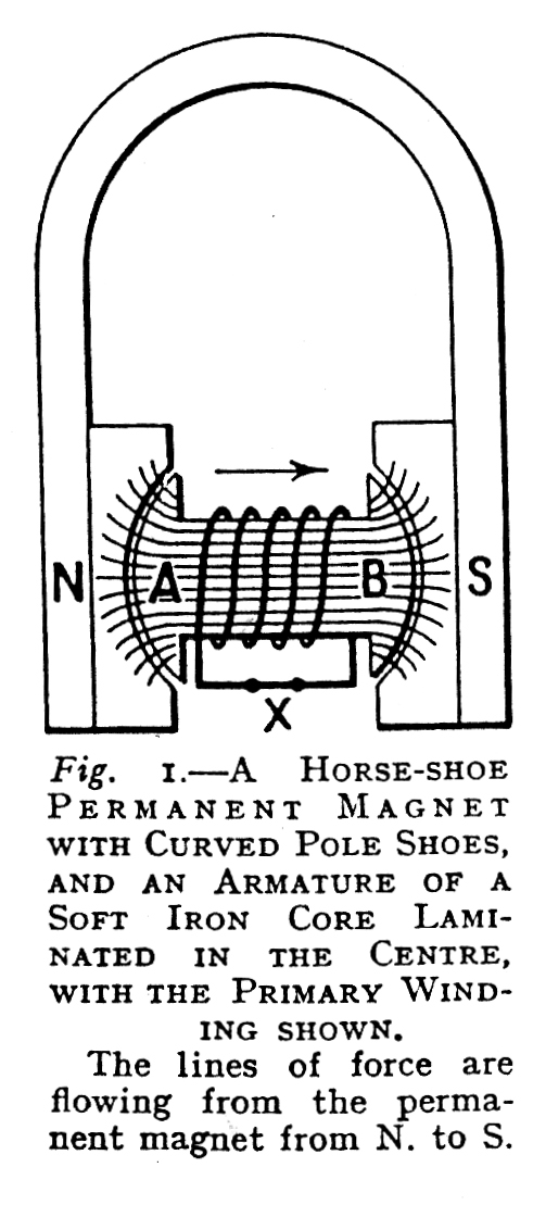
wire in a magnetic field. Fig. 1 shows a horseshoe permanent magnet with curved
pole shoes to conform with the periphery of the rotating armature. The armature
is constructed of a soft iron core laminated in the centre; this core is
thoroughly insulated with oiled silk and Empire cloth. The primary winding is
then wound on.
For the moment, we will only consider what happens in the primary winding.
Referring again to Fig. 1 you will observe that the lines of force are flowing
from the permanent magnet from N. to S. and are concentrated through the
armature core entering at the cheek A and leaving at cheek B. The reason for the
lines of force concentrating through the core is due to the fact that this is
the easiest path, iron being an excellent conductor of magnetic flux. Another
minor point must be borne in mind —that is, the armature cheek marked A becomes
a S pole and cheek B becomes a N pole, the law of magnetism being: like poles
repel, and unlike poles attract.
You will see in Fig. 1 that the primary is embracing the lines of force flowing
through the iron core, therefore to induce a current in the primary winding all
we have to do is to make the winding cut the lines of force. It must be pointed
out at this juncture that the primary circuit is a closed or complete circuit
through the contact breaker X.
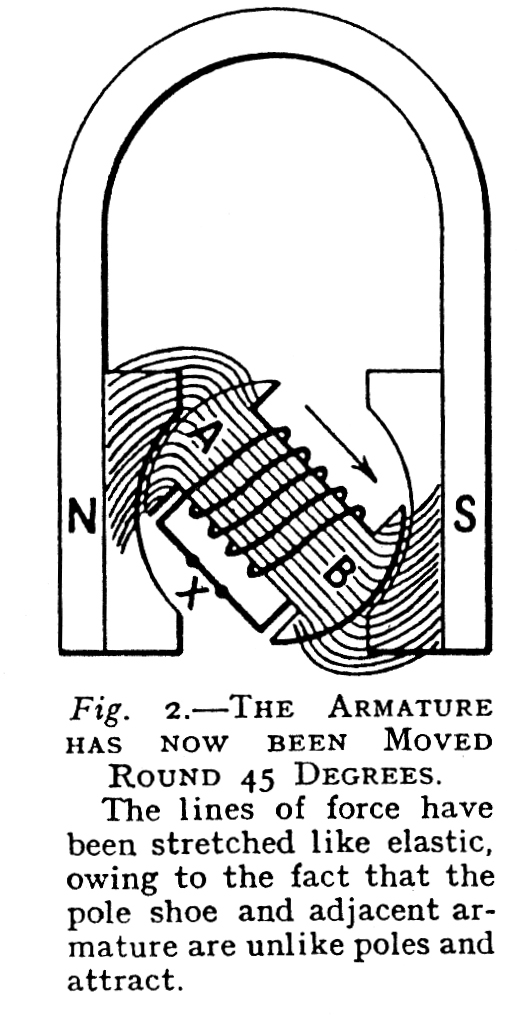
In Fig. 2 the armature has been moved round 45°—this has resulted in the lines
of force being stretched like elastic, owing to the fact that the pole shoe and
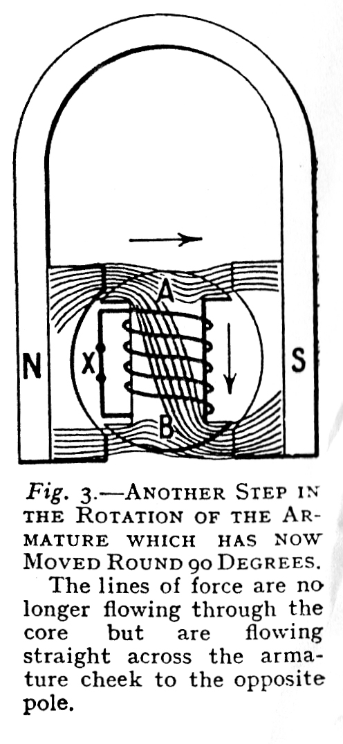
adjacent armature are unlike poles and attract. Fig. 3 shows another step in the
rotation of the armature which has now moved round 90° from the position in Fig.
1. If you now follow the lines of force in Fig. 3 you will see that some of the
lines are no longer flowing through the core but are flowing straight across the
armature cheek to the opposite pole. Therefore, the lines of force passing
through the primary winding have decreased and a current has been induced in the
primary winding. This in turn will tend to strengthen the magnetic flux in the
core and attract the lines of force flowing from the permanent magnets.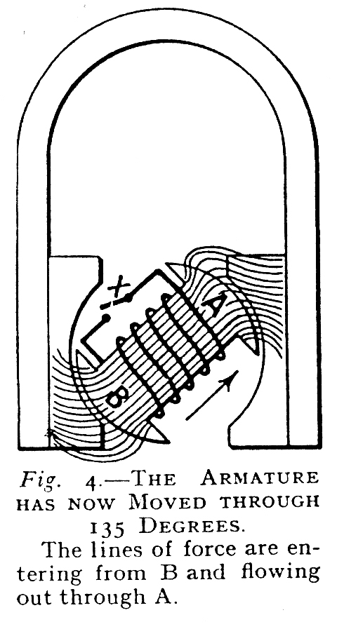
Let us now turn to Fig. 4. The armature has now moved through 135° and a
definite change will be seen to have taken place. The lines of force are now
entering the armature core from the bottom cheek B and are flowing out through
the cheek A, which is in the reverse direction to that in Figs. 1, 2 and 3.
Therefore, the lines of force flowing through or embraced by the primary winding
must have fallen to zero in one direction and started up in the opposite
direction; at the point of change the current in the primary will have reached
its maximum. It has already been pointed out that the greater the rapidity of
the collapse of the lines of force embraced by the primary winding, the greater
will be the voltage induced in the secondary winding.
The Operation of the Contact Breaker.
It is here that the action of the contact breaker comes into the
reckoning, as it will be understood that so long as the points remain closed,
current in the primary winding will be able to flow. This will in turn tend to
produce a magnetic flux in the core which we are endeavouring to decrease with
the utmost rapidity. Therefore, if we break the primary circuit at the precise
moment when the greatest change in flux density is taking place, we shall have
an almost immediate collapse of the lines of force flowing through the armature
core and windings, resulting in a very high induced voltage in the secondary
winding. This is further assisted by the condenser.
When Should the Contact Breaker Points Open?

Fig. 5 shows the position of the armature when the contact
breaker points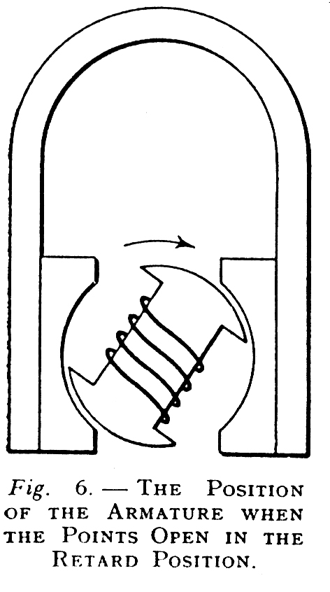 open in the advanced position, and Fig. 6 the position of the armature when the
points open in the retard position.
open in the advanced position, and Fig. 6 the position of the armature when the
points open in the retard position.
What Should be the Distance of the Air Gap?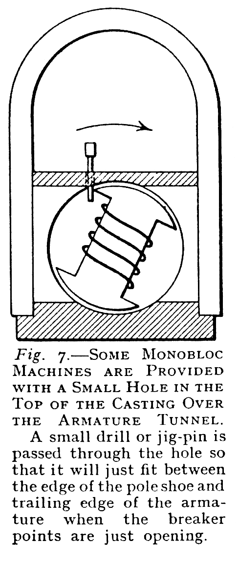
This depends on the type and construction of the pole shoe The modern
tendency is to use laminated pole shoes cast integral with a monobloc casting;
the earlier machines, however, had soft iron or cast iron pole shoes. The air
gap for laminated pole shoes is usually between 0.5 mm. and 1.5 mm; with solid
pole shoes it varies from 2 mm. to 3 mm. Some monobloc machines are provided
with a small hole in the top of the casting over the armature tunnel, through
which a small drill or jigpin may be passed, as in Fig. 7, so that it will just
fit between the edge of pole shoe and trailing edge of armature when the breaker
points are just opening.
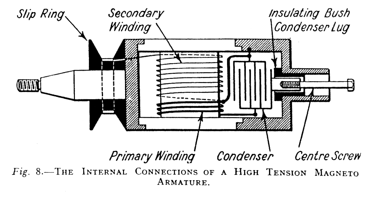
Fig. 8 shows the internal connections of a high tension magneto armature.
What is the Path of the Primary Circuit?
One end of the primary winding is earthed to the armature core either
on the core itself before commencing the winding or at the condenser lug that is
earthed to the end housing by means of a screw; the other end of the primary is
brought out to the insulated side of the condenser and is in circuit with the
lug receiving the centre screw of the contact breaker.
What is the Path of the Secondary Circuit?
One end of the secondary is connected to the primary winding and
consequently goes to earth. The other end is brought out to the slip ring and
conducted by a highly insulated conductor to the distributor.
Distribution of the High Tension Circuit.
The high tension circuit is conducted to the distributor, as already
stated; the conductor, however, is located in a gear wheel and rotates to
distribute the current to the respective plugs in turn.
If we turn back for a moment to Figs.1, 2, 3 and 4, it will be seen that from
Fig.1 to Fig. 4 the armature has completed nearly half a revolution; by
rotating the armature another 45° it will be in a similar position to Fig. 1.
This being so, it will be understood that two sparks per revolution of the
armature can be obtained.
A fourcylinder magneto runs at crankshaft speed but only one spark every second
revolution is required for each cylinder; therefore, the distributor rotor will
need to run at half the speed of the armature to obtain four sparks for one
revolution and so distribute the sparks to the required cylinders in one of the
following sequences—1, 2, 4, 3 or 1,3,4, 2, a spark being required for each half
revolution of the crankshaft.
In a six-cylinder engine, a spark will be required every third of a revolution
of the crankshaft. The magneto will therefore have to run at 1½ times the
crankshaft speed. The distributor rotating arm must run at half the speed of the
crankshaft and fire each cylinder in one of the following sequences—1, 4, 2, 6,
3, 5 or 1, 5, 3, 6, 2, 4.
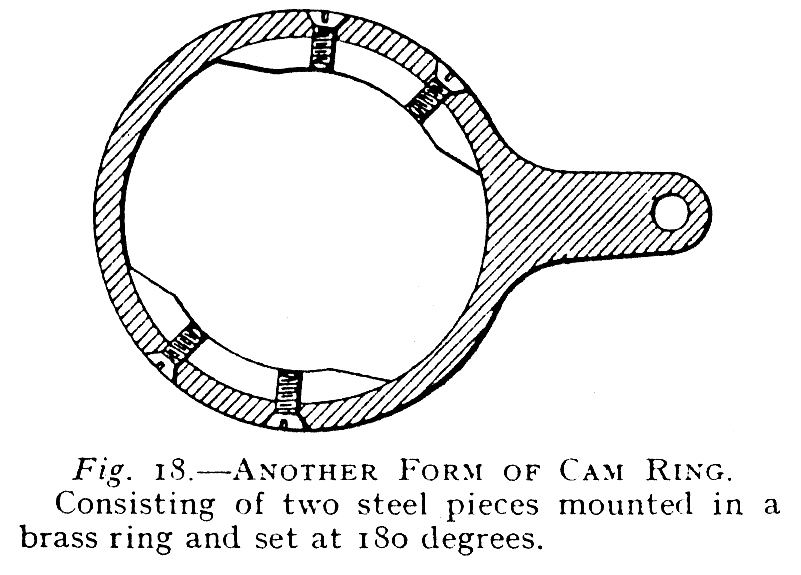
The Operation of the Cams.
On a two, four or sixcylinder magneto, two cams are arranged to open
the contact breaker at the required moment. The cams may be in the form of a
circular steel ring ground away on two sides, as shown in Fig. 17, or may be two
steel pieces mounted in a brass ring as shown in Fig. 18, and set at 180°.
It is very seldom that cams require renewing, but it is essential to see that
the breaker points open evenly on each cam. In the case of a onepiece cam ring,
it is impossible to make any adjustment to even up the cams should the points
open unevenly. Repairs and adjustments are possible, however, with cams that are
fitted as separate components in a brass cam ring.
To obtain the required amount of advance and retard, the cam is made moveable
over a range of from 15 to 30 degrees, some makes of machines having a greater
range than others. This movement is controlled by a pin or stop screw in the cam
box into which the cam ring fits, the inner lip of the cam ring being cut away
to allow for the required amount of movement.
 Modern Pole
Shoe Design.
Modern Pole
Shoe Design.
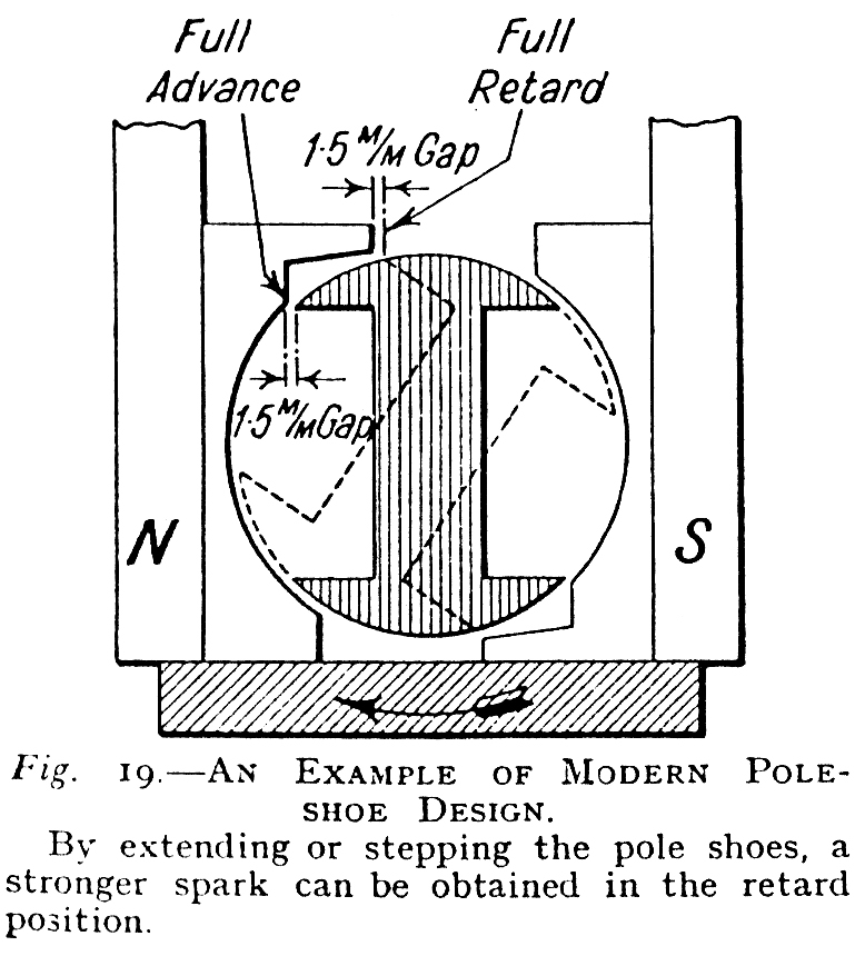
There has been a great advance in pole shoe design in recent years, and
it has been found that by extending or stepping the pole shoes, as in Fig. 19, a
stronger spark can be obtained in the retard position than was possible with the
early type of pole shoe, as shown in Figs. 1, 2, 3 and 4. Another development
has been the construction of laminated pole shoes.
Object of the Extended Pole Shoe.
The object of the extended pole shoe is to delay the reversal of the
flux so that an efficient spark can be obtained in the retarded position for
starting, for it is obvious that when the breaker points open in the retarded
position in a magneto having pole shoes as in Fig. 1, a considerable loss of
magnetic flux will have taken place in the armature core by leaking across the
armature cheek to the opposite pole, therefore when the points open and the
primary collapses the number of lines of force cut or changed in the winding
will be less, resulting in a lower voltage being induced in the secondary
winding. It must be understood that the induced voltage not only depends on the
rapidity of the collapse of the lines of force but also on the quantity
collapsed.
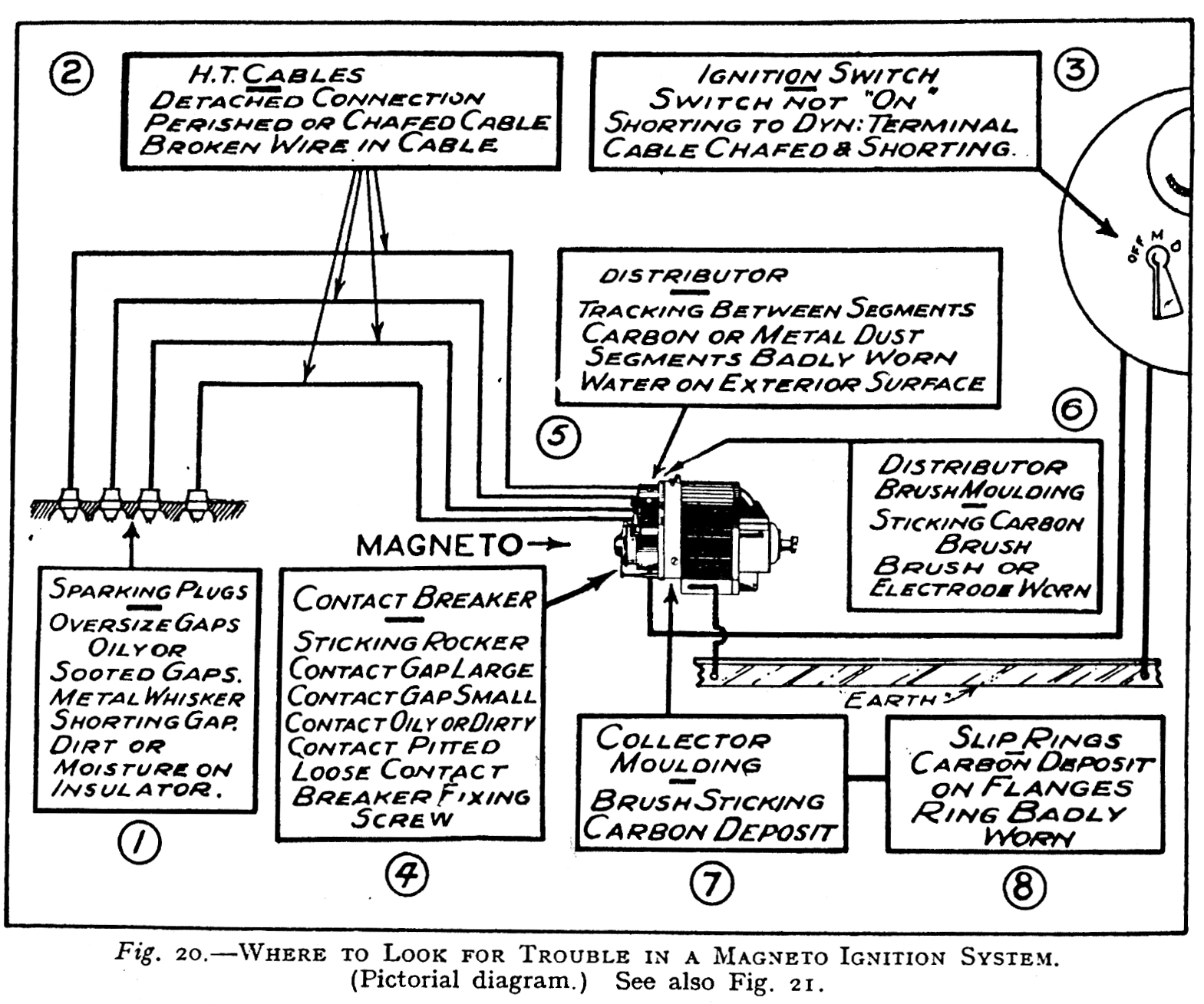
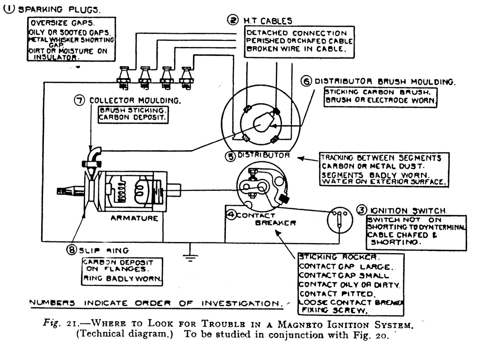
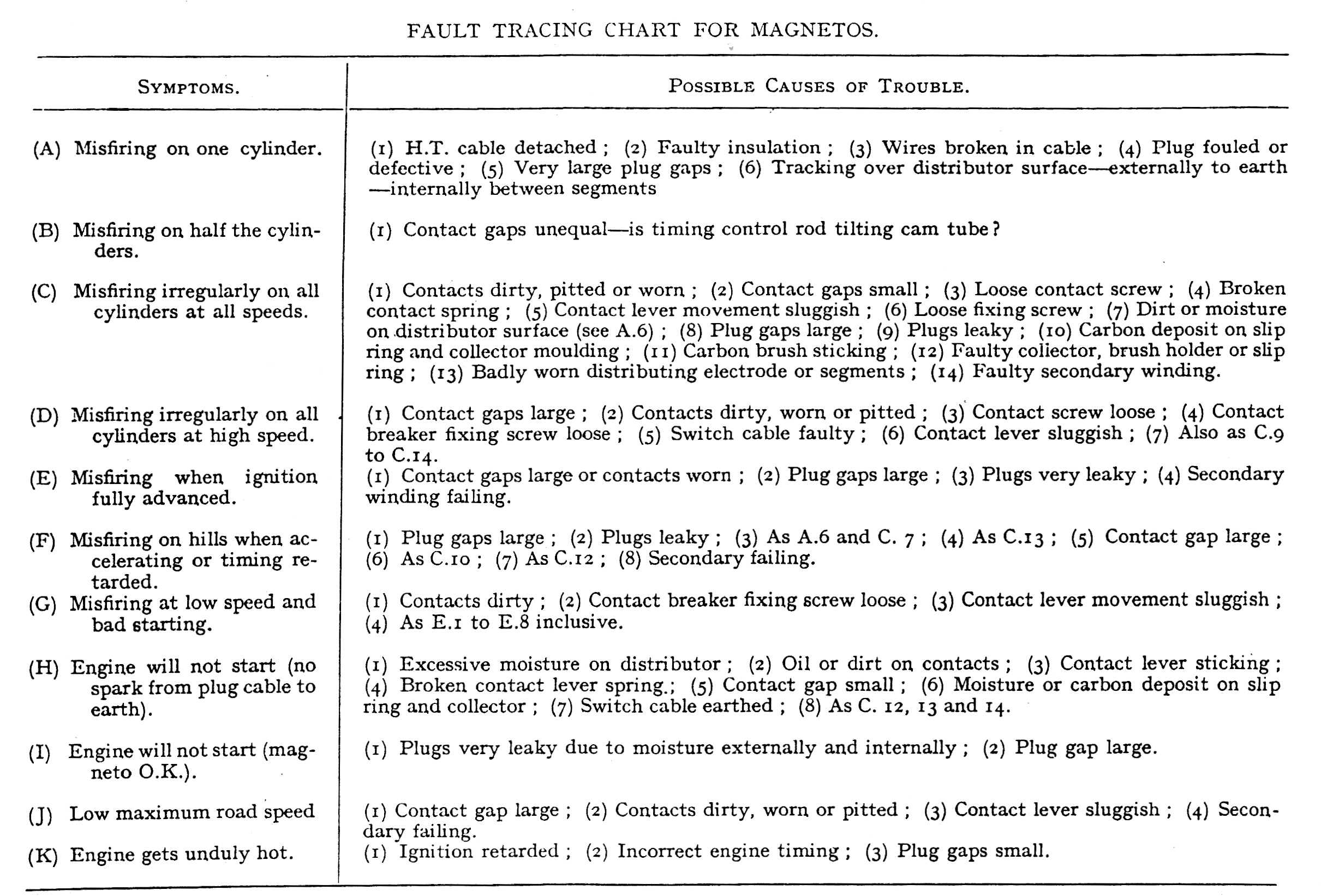
Testing and Fault Locating on H.T. Magnetos.
The usual symptoms are, of course, misfiring of the engine. A diagnosis
of this complaint is not so easily located with a magneto as with coil ignition,
and it is rather difficult to give ruleofthumb methods. However, the following
should be examined as a preliminary. If the engine refuses to fire at all the
switch wire should be disconnected from the contact breaker as the trouble may
be due to this wire having become chafed through, resulting in the primary being
permanently earthed; therefore, no break would take place in the primary circuit
when the points were opened.
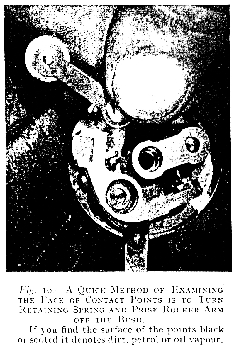
Plugs.
Run the engine for a few minutes to warm it up, then switch off and
feel the terminal top of each sparking plug; if you find that one plug is
considerably cooler than the rest, this indicates that the plug has not been
firing regularly, and it should be removed for inspection, and, if possible,
another plug fitted for test. Very often a plug will appear to be in order
except for the fact that it is slightly sooted; do not confuse sooted plugs with
carboned plugs. If a plug is badly carboned, you naturally rightly suspect that
it is defective, but if a plug is only sooted, as though the mixture was too
rich, you are apt to pass it over. This soot, however, is highly conductive, and
the spark will track up the sooted porcelain or mica to the barrel of the plug
and result in misfiring.
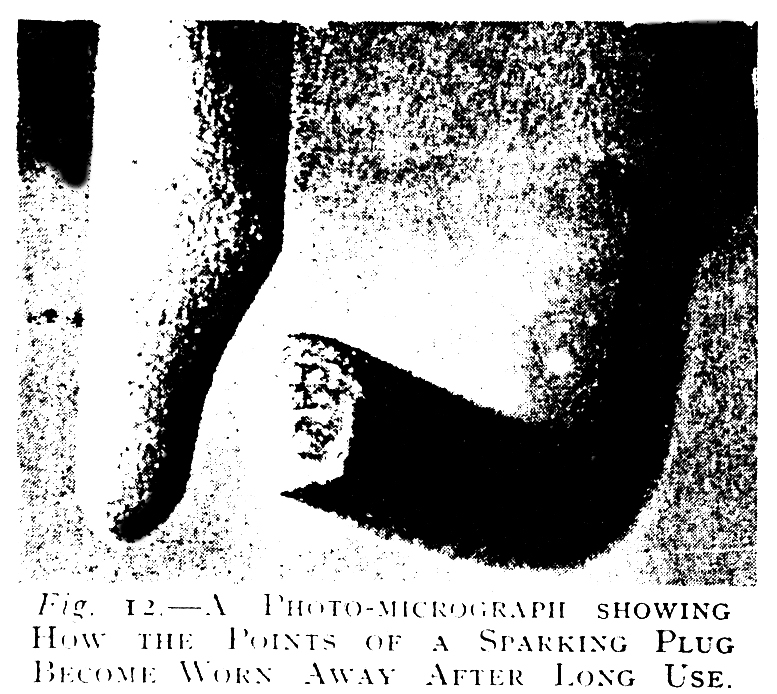
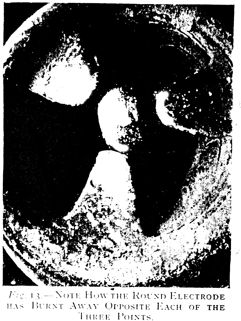
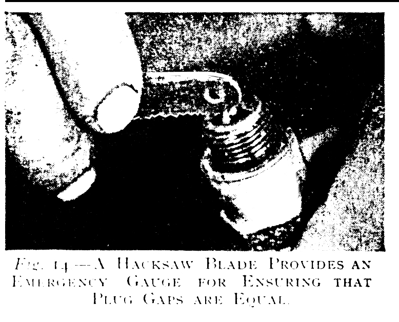
Too Great a Gap.
Another defect to look for in plugs is too great a gap due to the
electrodes having burnt back. This state of affairs will reflect seriously on
the secondary winding of the armature or coil, as the case may be, and is often
the cause of a breakdown in the armature or coil, owing to the increased
resistance to the H.T. spark.
Having made a preliminary test of the plugs as just described, and found them to
be all more or less of the same temperature, a further test can be made by use
of a good class neon plug tester. Having satisfied ourselves that the trouble is
not due to plugs, let us proceed to the next point where trouble is likely to be
found.
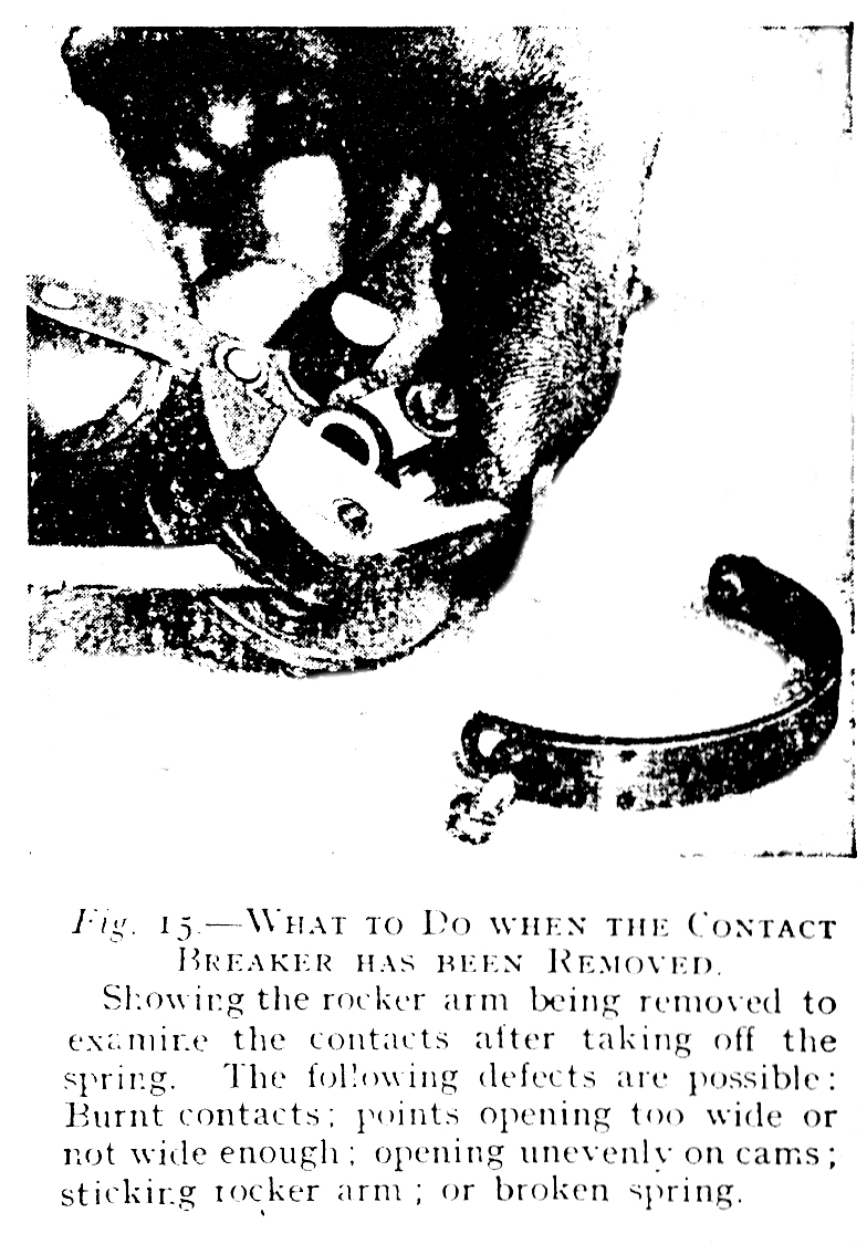
Contact Breaker Faults.
Remove the contact breaker cover and examine the contact breaker points
for the following defects: Burnt contacts; points opening too wide or not wide
enough (the correct setting being about 12 thou.); opening unevenly on cams;
sticking rocker arm; or broken spring. Any of the above defects, with the
exception of point adjustment, will necessitate the removal of the contact
breaker.
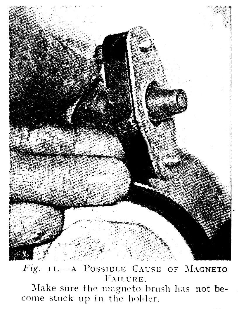
When removing this component, take care to see that the earthing brush is in
position and not stuck up. Another rather elusive contact breaker fault is due
to a badly worn fibre heel; this is the fibre block attached to the rocker arm
where it is actuated by the cams. As this heel wears down the points have to be
adjusted; on some types of contact breakers, it is possible for the adjustment
to be carried so far that it allows the rocker arm to foul the centre block in
which the stationary point is fixed. When this happens, continual misfiring
will take place and the only remedy is to fit a new fibre heel or complete
rocker arm, the latter recommendation being the most efficient, owing to the
fact that by the time this state of affairs has been reached the fulcrum pin of
the rocker arm will also have become worn. A rocker arm having a badly worn
fulcrum pin will wobble about badly when running, causing misfiring to take
place.
Assuming that we have found the contact breaker in order, let us now examine the
H.T. circuit.
Testing for Faults in the H.T. Circuit.
Testing the H.T. circuit of a magneto while it is in position on the
car is rather an unsatisfactory proposition, but nevertheless it has to be done
when it is not convenient to remove the magneto for a bench test.
The procedure recommended is as follows: remove a wire from one plug and lay it
on the cylinder so that the spark may jump to earth; start the engine, then hold
the disconnected plug lead about a 1 in. from the cylinder. If the H.T. circuit
is in order, the spark should jump this gap easily. If it does not, then the
magneto is definitely defective. Do not be misled by the fact that you can
obtain what you assume to be a good spark if you hold the plug wire say 1/8 in.
from the cylinder, as this spark will not be strong enough to jump the plug
points under compression. You must obtain a spark of at least ¼ in. for the plug
to fire satisfactorily under compression. On no account should the engine be
allowed to run with the disconnected plug lead in such a position that a spark
cannot jump to earth.
From the foreg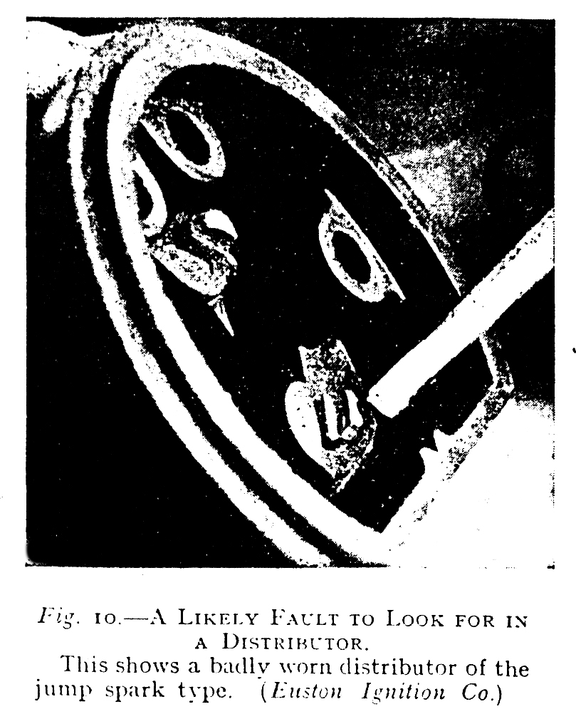 oing
remarks it will also be clear that the. operation of removing all the plugs and
laying them on the top of the cylinders with the plug leads connected, then
cranking the engine and observing whether they are sparking or not, will be no
criterion as to the condition of the magneto.
oing
remarks it will also be clear that the. operation of removing all the plugs and
laying them on the top of the cylinders with the plug leads connected, then
cranking the engine and observing whether they are sparking or not, will be no
criterion as to the condition of the magneto.
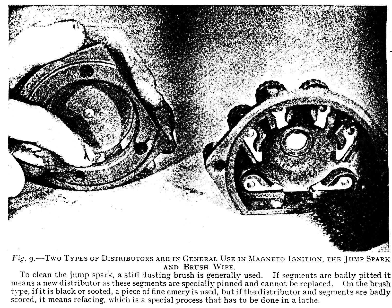
 FAULTS
WITH DISTRIBUTOR BOARDS, ROTORS AND PICKUPS.
FAULTS
WITH DISTRIBUTOR BOARDS, ROTORS AND PICKUPS.
Should you find on testing the high tension that the spark is weak and
will only jump a small gap, the following components should be examined for a
possible visible fault.

Distributor Board.
Look for tracking between segments, tracking between cable terminals or
puncture at base or adjacent to fixing clips (see Fig. 22). The foregoing faults
are usually visible but in cases of doubt they can be tested on the H.T. test
previously described.
Rotors.
This component can usually be withdrawn after removal of the
distributor board; care must be taken not to let the carbon brushes fall out or
fall into the magneto. The most common failure with this component is a puncture
in the insulation, allowing the spark to jump to earth. A breakdown of this
description is very rare and is more often brought about by the mishandling of
the rotor, resulting in it becoming cracked.
The Pickup.
This component is situated at the slip ring end of the armature and
picks up the H.T. current from the slip ring.
Defects to look for in the pickup are puncture in insulation, tracking, carbon
brushes stuck up, broken or missing altogether. Let us assume that the
foregoing components have tested O.K. but still we obtain no results from the
magneto. The only obvious course is to remove the magneto for further bench
tests, which is dealt with in a later section.