The intake hole in the Box’s manifold (and all standard Sevens, I think) is about 1 inch. Whilst 1¼“ SUs are readily available at autojumbles and can be fitted without a problem, clearly a 1” or, even better, a 11/8” is preferable. The 1” can easily be identified as having no outside flange whereas the 11/8” does. I was lucky to pick up a 11/8” at Beaulieu so the rest of this article will be about fitting it.
Will it bolt straight on?
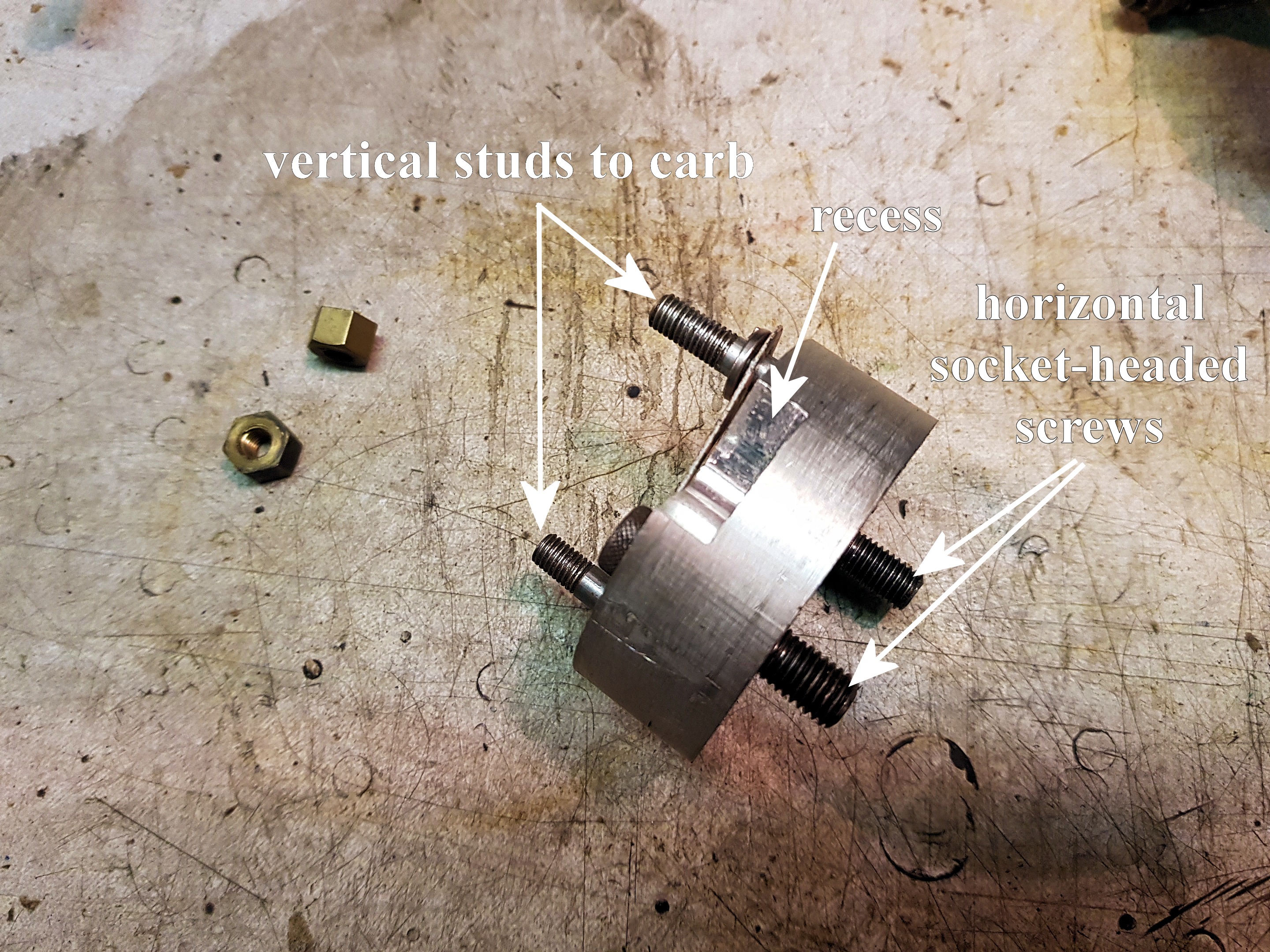
Unfortunately, not! The holes in the inner flange of the SU to go over the
 studs are vertically placed whereas the studs in
the manifold are horizontal, so we need a 90o adapter. This is
easily made on a home lathe or is available from the usual A7 suppliers (e.g.
Tony Betts at Seven Counties Austins and
David Cochrane at A7 Components).
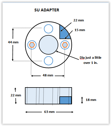
If you’re making one yourself, note the small cut-out section which is necessary
to accommodate the throw of the throttle lever. See dimensions at end. However,
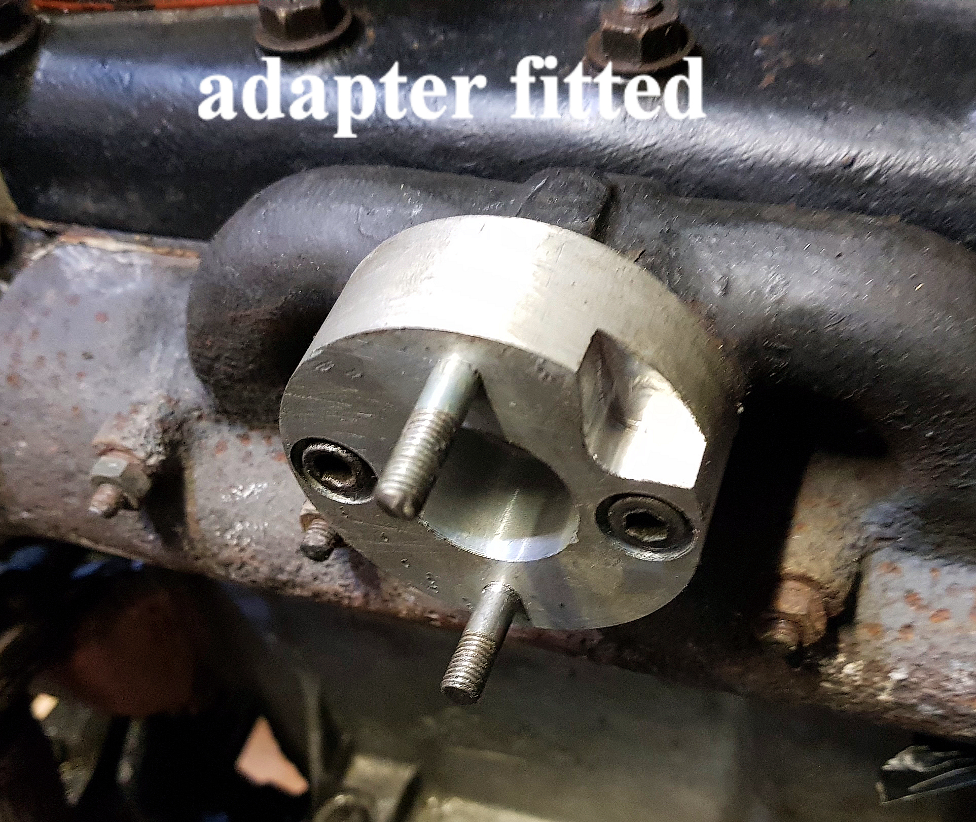
with the adapter, yes, the SU then bolts straight on.
studs are vertically placed whereas the studs in
the manifold are horizontal, so we need a 90o adapter. This is
easily made on a home lathe or is available from the usual A7 suppliers (e.g.
Tony Betts at Seven Counties Austins and
David Cochrane at A7 Components).
If you’re making one yourself, note the small cut-out section which is necessary
to accommodate the throw of the throttle lever. See dimensions at end. However,
with the adapter, yes, the SU then bolts straight on.Do the A7 accelerator lever and choke cable fit directly?
Yes!
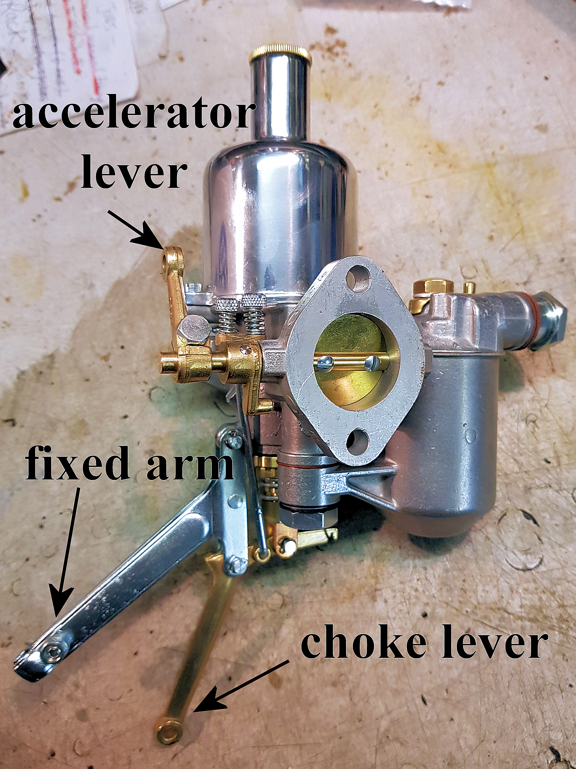
Choke: The SU carb has its own fixed arm and sprung choke lever so the A7 stiff wire choke cable simply goes through the hole in the fixed arm (just for guidance) and pulls directly on the choke lever, in the correct direction. The only thing needed is something to grip the wire to stop it pulling out of the choke lever. You may be able to use the existing one on the Zenith, but I had a spare in my box of bits. If you have a flexible choke cable in a sleeve, then the hole in the fixed arm will accommodate the nipple-end of the outer cable.
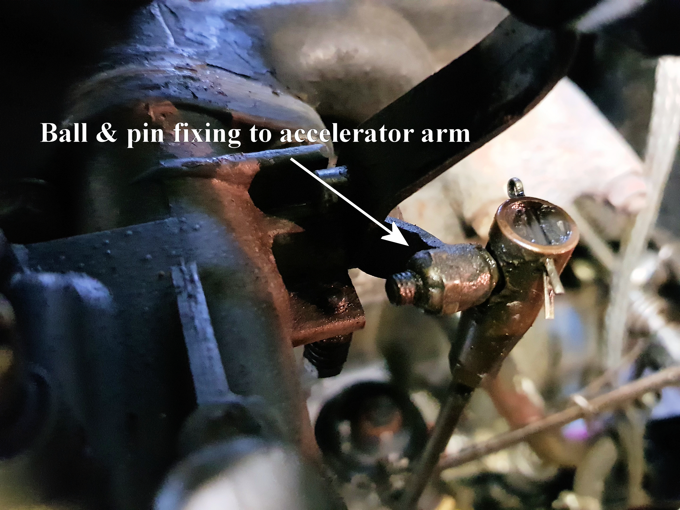
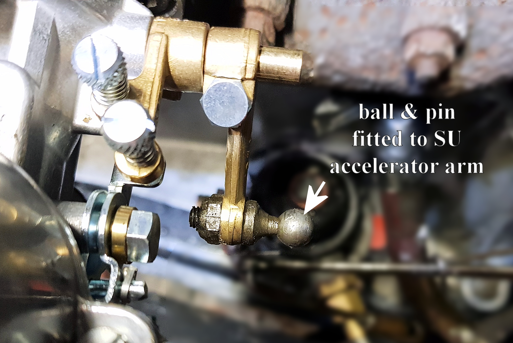
Accelerator arm: The Zenith carb has a ball and pin which bolts to its throttle arm and fits in the vertical accelerator lever of the car. The SU has an exact hole to take the ball and pin and it can easily be adjusted vertically on the throttle spindle to get the right height. I was warned that I might need to organise the A7 accelerator lever to have a bigger movement to fully operate the SU butterfly, but the 11/8” seems to be fully opening and closing with the standard A7 accelerator mechanism. (Perhaps the 1¼ “is different.)
In order to remove the ball and pin from the Zenith carb, I first removed it from the vertical throttle arm. This nearly ended in disaster! First, remove the split pin which is preventing the head of the accelerator arm from rotating and unscrew the head using the screwdriver slot at the top. This is where the danger arises – under the head is a strong spring with two tiny cups which surround the ball end of the pin. The spring won’t suddenly jump out until the ball is removed by pushing it down and pulling it sideways but you may a) lose the upper cup lodged in the head and b) lose your eye when the ball does come out and the spring is released. For me, the bottom cup went spinning through the air, right over the car and far away only to be retrieved 20 minutes later. I now wonder if it was possible to remove the pin from the Zenith without taking the head of the accelerator arm to pieces. The Zenith can now be removed from the manifold.
Fitting the SU:
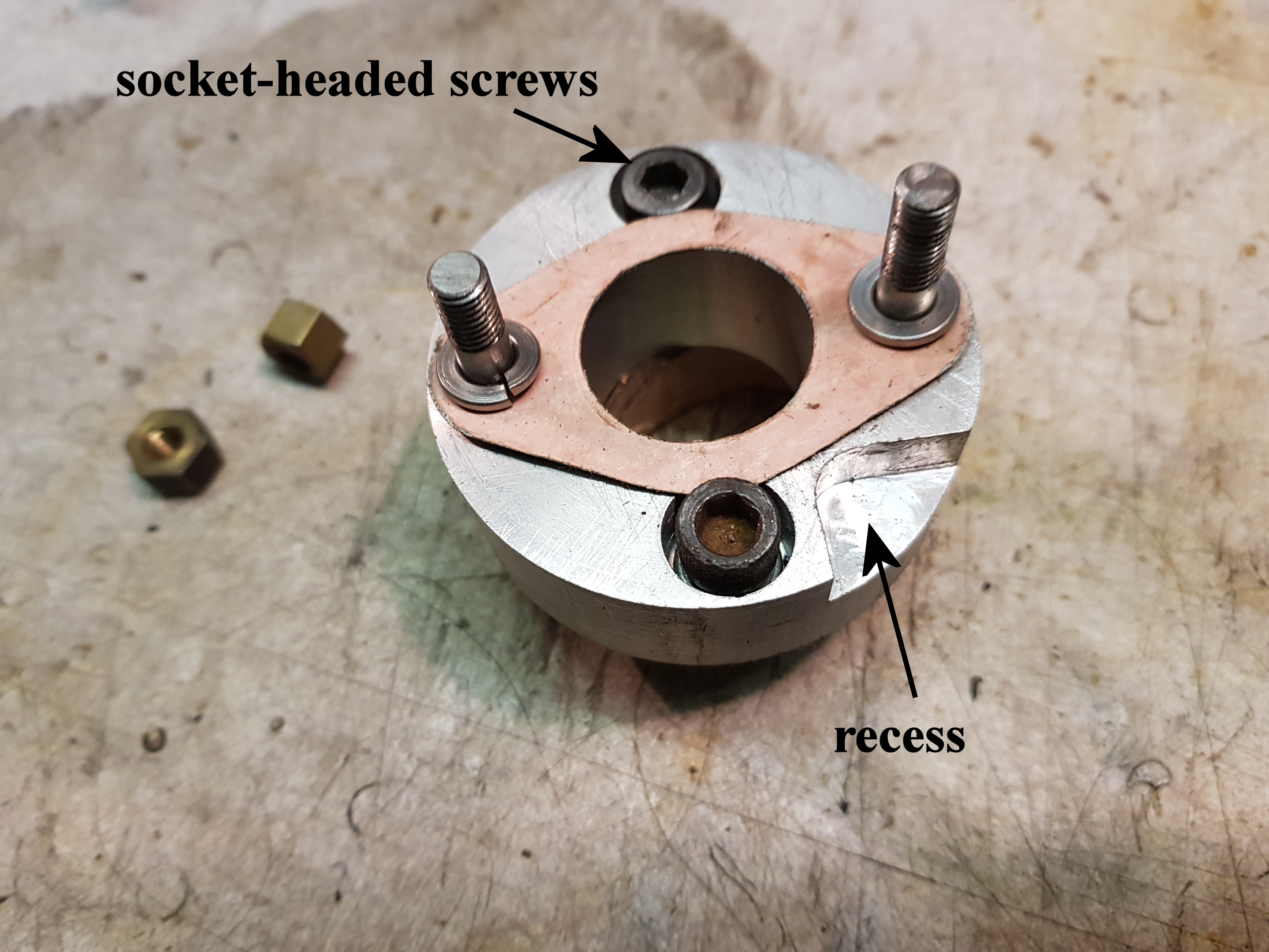
Because the inner flange of the SU will be a tight fit on the outer face of the adapter, you can no longer use the existing studs but, instead, have to use hexagon socket -headed, countersunk screws (5/16 BSF 1 inch long) that screw down into the threaded holes left when the studs have been extracted. My two studs came out relatively easily but a little heat on the manifold may be needed. Be careful, of course, not to shear-off a stud. Making sure the two, new bolts, facing outwards to engage the SU are in place, the adapter can then be firmly screwed to the manifold with a suitable gasket and goo. The SU can now be slipped over the protruding bolts with another suitable gasket and goo and the nuts tightened down. The lower nut gave me the most grief of the whole job as the nuts cannot be put into place with the SU pushed home. However, with a lot of patience and a lot of fiddling the SU was firmly bolted in place.
The ball pin is easily bolted in place, with the nut gripping the spindle left firm, but not tight at this stage, so the levers can be adjusted to fit. Now for the tricky bit – getting the ball back into the head of the accelerator lever on top of the spring and lower cup by pushing the cup
 down from above with an electrical screwdriver whilst pushing the head
over the ball. Once in place, pressure is taken out of the system and the
top cup and head can screwed down and the split pin replaced.
down from above with an electrical screwdriver whilst pushing the head
over the ball. Once in place, pressure is taken out of the system and the
top cup and head can screwed down and the split pin replaced.With the spindle nut a firm fit, you can now push down the throttle connecting lever so that the butterfly is fully closed when the accelerator arm is at the bottom of its travel. After the trial run, I had to lift the accelerator arm very slightly so that its spring held the butterfly more firmly shut – when I lifted my foot off the accelerator, the butterfly wasn’t closing properly and the revs didn’t die away enough.
The choke cable is an easy fit but ensure that it is fully home before tightening the keeper.
And that’s it! Mine started first time and, after allowing the engine to warm up on a fast tick-over, I adjusted the mixture by ear to produce the fastest setting (rather like setting the timing by ear) and then took it for a good run. (For SU novices, the large nut at the bottom of the SU is easily screwed upwards by hand to weaken the mixture and downwards to enrichen it. The setting is done at fast tick-over.) Checking the plugs on return, I got a grey electrode and black surround which is probably about right. Vince swears by ColorTune but my old one only has a 14 mm thread so I’m waiting for an 18 mm adapter from E-bay (just type in “Spark Plug Thread Adapters 18mm down to 14mm”) to see how close I’ve got by ear.
The actual job took only a day having got all the bits assembled but, whilst the Zenith was off, I took the opportunity to check the tappets and try to seal the valve chest cover a bit better to stop the annoying dribble of oil after every run and cleaned out the inlet port with a wire brush and smoothed a raised part of the casting with a rotary file.
Joining up the fuel pipe:
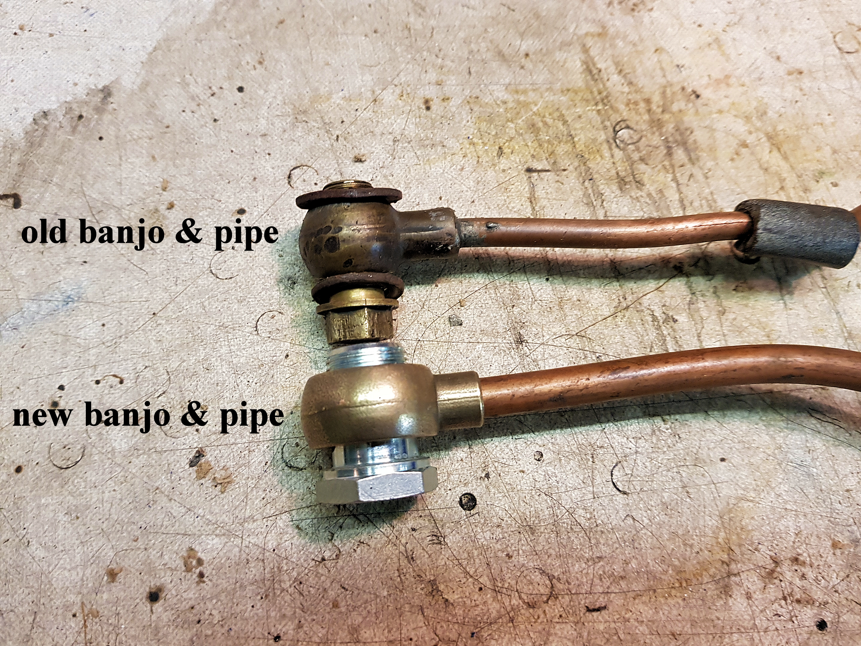
The SU banjo is much larger than the one on the Zenith and so is its input nozzle requiring a larger diameter pipe (5/16” o/d) than the existing one (1/4” o/d) and a larger nipple at the fuel pump end (both available from Seven Workshop). However, to my surprise, the larger nipple was a petrol-tight fit to the fuel pump which, therefore, needed no alteration to the output port. I could have used the existing pipe as a model for the new one but took the opportunity of rotating the top of the float chamber to take the banjo, and thereby the petrol pipe, further away from the manifold and exhaust downpipe to help reduce vaporisation in the pipe. The only points to note about soldering the pipe into the banjo is to make sure you’ve got the alignment right if you’ve already bent the pipe to shape and, more importantly, that the indented groove that takes a recessed washer is facing outwards towards the large nut. (I got it wrong and had petrol squirting everywhere until I worked out what the problem might be and had to re-solder the banjo rotated by 180o.)
Needles:
Ian Mason-Smith has done quite a bit of research on which SU needles are appropriate for A7 engines – see our website http://www.da7c.co.uk/technical_torque_articles/su_needles.htm and there is a very useful interactive webpage (http://www.mintylamb.co.uk/suneedle/.) where one can type in up to 3 needles at a time by name and a graph will compare their running characteristics. My SU came with an MO needle so I started from the premise that if it was good enough for the previous owner, it was probably good enough for me. On the Burlen’s website (http://sucarb.co.uk/technical-jet-needle-recommendations), one can search for which needles were fitted as original equipment and my MO was fitted to 1933 Morris 8s and Austin Healy Sprites, so I’m going to stick with the MO. Ian uses EB (which looks to be almost identical to my MO and was also used on Austin Healy Sprites) and AN needles but in 1¼“ carbs with springs (the 11/8” doesn’t have a spring). With
 his
11/8”, Bernard uses an M..
his
11/8”, Bernard uses an M..Burlen’s:
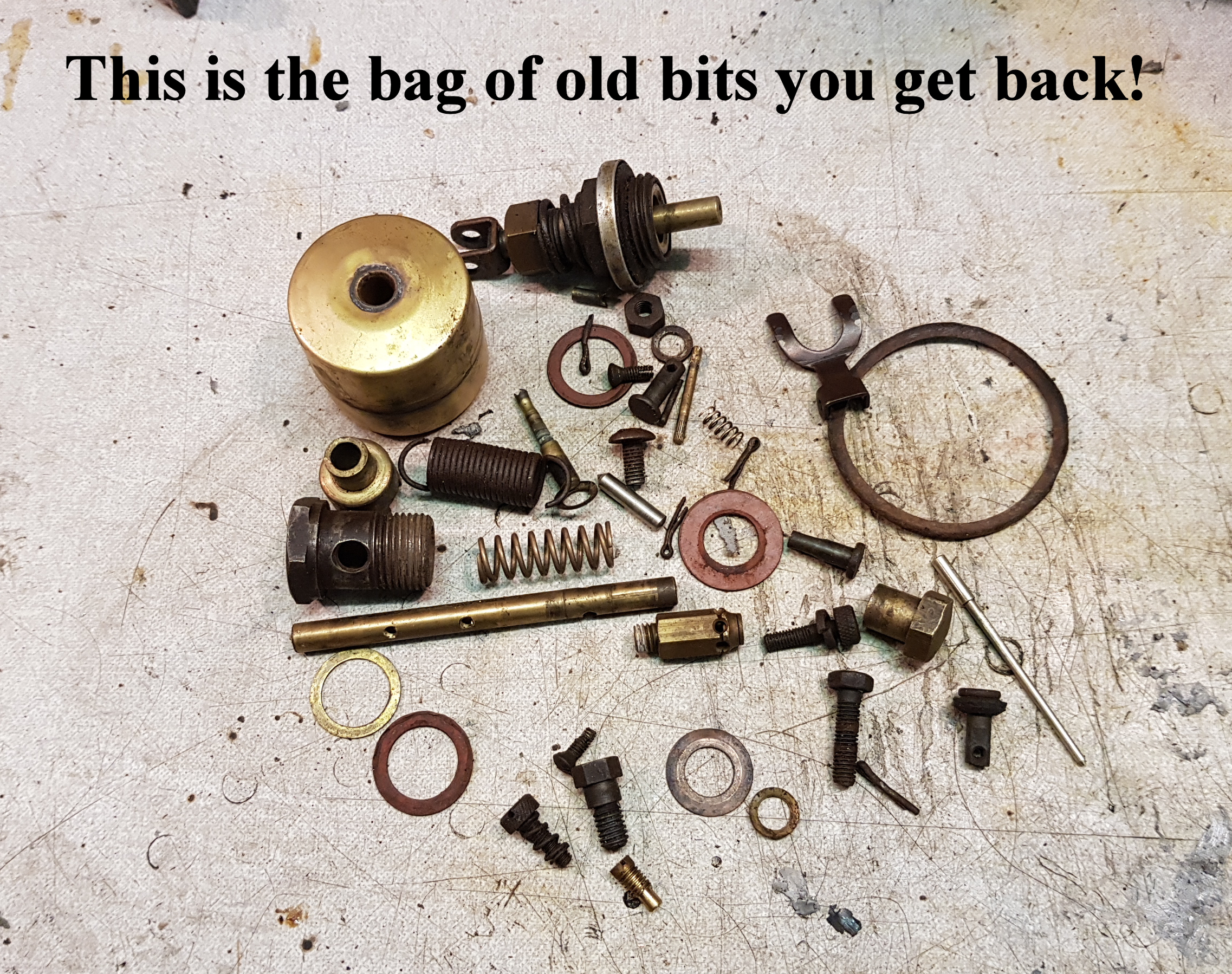
The SU was in a rough old state when I bought it so there were three options – a) leave it alone but just clean it up; b) buy a kit of parts and do it myself; or c) get Burlen’s to completely refurbish it. I chose the latter.
There are now two sides to this, and you will have to choose – the total cost was an eye-watering amount but the bag of old bits I got back contained every screw, spring and split pin; spindle, butterfly, needle, float, float needle, jet etc etc. In other words, everything had been changed except the body and piston and the body was polished to look like chrome. I even got a new banjo and filter thrown in as mine was missing. Was it worth it? Only you can decide. I’m absolutely thrilled, albeit a little bit poorer.
Running:
ALL IN PLACE PHOTO
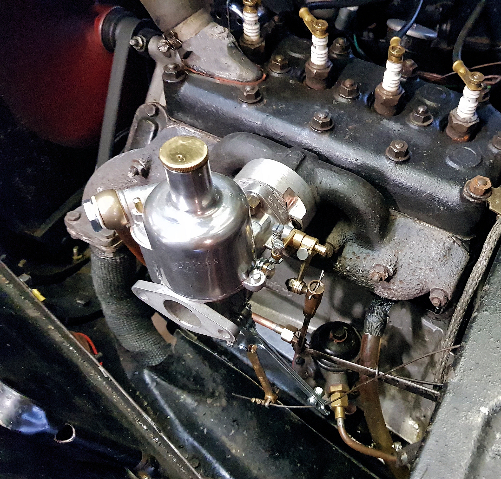
Everyone who has made the conversion used the phrase “smoother running”. It’s difficult to quantify this but I have to agree. The car did run much more smoothly, with an absence of having to double-declutch and, whilst there was little improvement in top speed (is this the limitations of the whole car rather than just carburation?), there was a distinct improvement in torque giving quicker acceleration and more pull up hills. It also now starts “on the button” without having to prime the fuel pump or wind the handle. Am I pleased I made the conversion? You bet. Early days yet but, at the end of the day, everything can easily be reversed if not.
David (Bodger) Whetton