The MOT has now passed into history as far as the Austin 7 is concerned. The need for owners to give their cars a periodic and detailed inspection is now more important than ever. The onus is on us, the owners, to ensure our cars are in a road legal condition. A voluntary MOT would not let you off the hook if you were stopped by the fuzz (now more likely than before) and found to be driving a defective vehicle. We are looking here at probably one of the most neglected parts of the car, the steering side tube or drag link, as most of us know it.
Grease nipples were fitted on later cars, but
previous to those it was not that easy to lubricate the moving parts and many
are found to be in a poor condition with heavy wear and rust. I have seen some
that were loose and worn so badly that they were coming to the point of
detaching themselves from the steering box or steering arm. I will run through
the strip and removal and point out the defects you are most likely to come
across.
Before you start, have a look under the car and put
the steering on full left and right hand lock and observe how close the drag
link is to the bodywork and note if it is straight or bent. If bent as many are,
decide if you will have enough clearance if you straighten the tube. Pre 30s
cars have flimsy flitch plates that will ‘give’ if contact is made with the drag
link when traversing rough ground on full lock; many show ‘witness marks’ where
this has occurred (this would have been a failure on the MOT if noticed). Boxes
and Ruby models have more substantial bodywork and seem to suffer more from bent
drag links, maybe due to settlement of the springs reducing the clearance
between body and steering tube. If you have decided to straighten one that is
bent it is best done by putting the tube in the vice and using another larger
tube slipped over it as leverage to work along until is straight, put the end
cap on the end to take pressure off the thin ends of the tube or problems will
occur when you are fitting the thrust blocks on reassembly. Using a hammer is
not recommended, as they can be quite stiff to bring back into shape. Its best
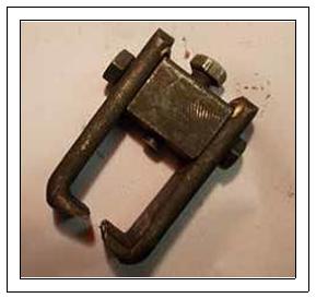
to remove the assembly from the car, so start by removing the split pins and
castellated nuts from both the ball pins. You will need a suitable puller (I
don’t like hammering old metal, especially on anything to do with the steering)
to remove the ball pins from the steering box drop arm and the steering arm as
they are on a taper fit and can sometime s be very tight. Pic. A shows one I
made up for the job many years ago. Back on the bench a quick inspection is sure
to reveal that a previous bodger has been at work with his favourite tools, a
hammer and cold chisel to remove the end caps, you will also find he uses these
on the large flat nuts on the back axle as well as the flywheel and front
crankshaft nut! Undo the ¼” bolts that hold the end caps on, first defect is
likely that the threads are shot due to them being hammered in with the end caps
misaligned by our bodger friend on a previous occasion, replace with new. A 12
Pic. B shows a half round aluminium drift I use for removing the end caps
without damage. Recover the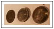 chamfered thrust disc and any packing washers or shims (Pic. C) as well as the
loose thrust block from each end of the drag link, it never ceases to amaze me
what you find inside, one I stripped for this article had 6 spring washers
instead of a spring and another had a valve spring cup instead of the chamfered
disc, and even a pair of metal coat buttons in the one that was on my Chummy,
they had obviously covered many miles like that so what ‘can’ you say! Now for
the hardest part of the job: removing the fixed thrust blocks. If you are lucky
they may just fall out by banging the end of the shaft on the bench. Try this at
both ends as you only need to get one out to enable you to put a rod inside the
tube and knock the remaining one out. Likely as not they will both be rusted
solid with no visible means of removal. Pic. D shows an 1/8” punch held on an
angle inside the bolt hole to knock the fixed block forward as much as possible
before the hole closes up on the punch. Get yourself a proper punch as 3 ” nails
and drills just will not do the job if they are really tight. Pic. E shows the
front edge of the thrust block that has now moved forward enough to grind a
small notch into it, this will allow you to use the punch in the notch to drive
the block forward a little more. Pic. F shows a screwdriver against the other
end of the block revelled in the bolthole to lever it forward and out. Drop the
chamfered thrust disc and any packing washers or shims (Pic. C) as well as the
loose thrust block from each end of the drag link, it never ceases to amaze me
what you find inside, one I stripped for this article had 6 spring washers
instead of a spring and another had a valve spring cup instead of the chamfered
disc, and even a pair of metal coat buttons in the one that was on my Chummy,
they had obviously covered many miles like that so what ‘can’ you say! Now for
the hardest part of the job: removing the fixed thrust blocks. If you are lucky
they may just fall out by banging the end of the shaft on the bench. Try this at
both ends as you only need to get one out to enable you to put a rod inside the
tube and knock the remaining one out. Likely as not they will both be rusted
solid with no visible means of removal. Pic. D shows an 1/8” punch held on an
angle inside the bolt hole to knock the fixed block forward as much as possible
before the hole closes up on the punch. Get yourself a proper punch as 3 ” nails
and drills just will not do the job if they are really tight. Pic. E shows the
front edge of the thrust block that has now moved forward enough to grind a
small notch into it, this will allow you to use the punch in the notch to drive
the block forward a little more. Pic. F shows a screwdriver against the other
end of the block revelled in the bolthole to lever it forward and out. Drop the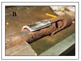 punch into the tube and shake it up and down knocking the other one out of the
opposite end. If this fails you will need a long rod to punch it out. That’s all
the hard bits out of the way so go and have a cup of tea. That is what I did as
it was minus 2 degrees in my garage when I was doing this for the photos!
punch into the tube and shake it up and down knocking the other one out of the
opposite end. If this fails you will need a long rod to punch it out. That’s all
the hard bits out of the way so go and have a cup of tea. That is what I did as
it was minus 2 degrees in my garage when I was doing this for the photos!
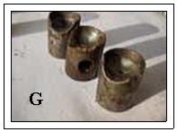
Next have a good clean up and thorough inspection, hold the tube up to the light and look inside for rust pitting (unlikely) check the ball pins are round (unlikely, the ones on this one were worn 60 thou. oval with deep grooves worn in the necks) check the four thrust blocks for chipping and wearing thin on the edges as shown in (Pic. G) check springs for compression and breakages (Pic. H). So if this was the case chuck the lot in the bin and buy new ball pins thrust blocks and springs. The chances of the result being any different than this is unlikely so suggest you buy the bits before you start! The next thing to do is inspect the ‘keyhole’ slots in each end of the tube, they are unlikely to have any cracks but do check for rust thinning on the tube ends as the last couple of inches are machined with an undercut to give location for the fixed blocks and are therefore thinner than the rest of the tube. The edges of the ‘keyhole’ slot will probably have worn to a knife
-edge in places (this can wear a groove in the neck of the ball pin), lightly file back to thicker metal with a nice rounded edge. When finished should look like (Pic. I) Note: you should not be able to put the new ball pin though the narrow ends of the slot, if you can, get another draglink. Dress any lumps around the bolt holes and run a ¼” drill through the holes and deburr. Turning to the end caps, as mentioned previously they are likely to have been butchered in the past. File the ends flat, clean up the bore and give all of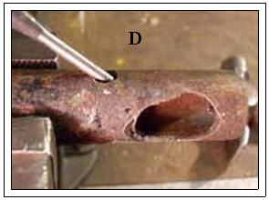 the dents and sharp edges a smoothing off with a fine file, also pay particular
attention to the edges of the slots as if worn sharp these can also cut into the
ball pin necks. Dress any lumps around the bolt holes and run a ¼” drill through
the holes and file down any burrs, they should then slide on and off the tube
easily by hand. The slots in the end caps (Pic. J) can wear badly, especially
near the end, if it is bad enough to allow the ball pin head to go through (or
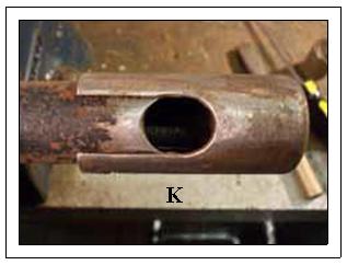
nearly through) put it in the bin and get another in better condition.(Pic. K)
shows it all looking nice and neat ready for reassembly. The Austin Service
Journal says to arrange assembly so that you have between 1/64” to 3/64”
free play in the joint when bolted up. This is not always easy to achieve as the
replacement parts may not be identical to the originals, I have lots of new old
stock ball and block sets from multifarious now defunct manufacturers (‘Remax’
as an example) that seem to vary, especially the spring lengths so I will need
to give two versions of the rebuild process. I have never had any modern sets so
the dents and sharp edges a smoothing off with a fine file, also pay particular
attention to the edges of the slots as if worn sharp these can also cut into the
ball pin necks. Dress any lumps around the bolt holes and run a ¼” drill through
the holes and file down any burrs, they should then slide on and off the tube
easily by hand. The slots in the end caps (Pic. J) can wear badly, especially
near the end, if it is bad enough to allow the ball pin head to go through (or
nearly through) put it in the bin and get another in better condition.(Pic. K)
shows it all looking nice and neat ready for reassembly. The Austin Service
Journal says to arrange assembly so that you have between 1/64” to 3/64”
free play in the joint when bolted up. This is not always easy to achieve as the
replacement parts may not be identical to the originals, I have lots of new old
stock ball and block sets from multifarious now defunct manufacturers (‘Remax’
as an example) that seem to vary, especially the spring lengths so I will need
to give two versions of the rebuild process. I have never had any modern sets so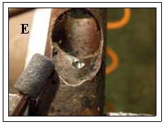 have no idea how close they are to the original pattern. Start the assembly by
tapping the fixed thrust block (the one with the hole) into the tube with a
brass drift, use some anti-seize grease such as ‘copperslip’ on the sides of the
thrust block, and align the holes using a podger bar and make sure a ¼” bolt
will go through easily. Put the ball pin in the keyhole slot and slide the loose
thrust block into the tube and push up tight to the ball pin. At this point note
if the thrust block is sticking out proud from the end of the tube or just flush
with the end, if this ‘is’ the case fit the chamfered thrust disc into the end
cap (chamfer facing the end
of the cap) a blob of ‘Vaseline’ is good for keeping it in place. If the
distance piece was missing from your assembly you will need to make one up, they
are around 1/8” thick (not sure if new ones are available). Slide the cap on to
the tube until it touches the end of the thrust block. Observe the relative
positions of the bolt holes in the tube and cap, add or remove shims or washers
until the bolt hole in the cap has just gone ‘past’ the hole in the tube by
1/32” i.e. if you then pull it back 1/32” and put the bolt in the joint will
rattle slightly. If this has gone to plan remove the cap and shims and put to
one side for reassembly. Put the new spring into the end of the thrust block,
check that the spring sticks out from the end of the block by 1/8”to 3/16”,
using a piece of wood or hammer shaft push on the spring making
have no idea how close they are to the original pattern. Start the assembly by
tapping the fixed thrust block (the one with the hole) into the tube with a
brass drift, use some anti-seize grease such as ‘copperslip’ on the sides of the
thrust block, and align the holes using a podger bar and make sure a ¼” bolt
will go through easily. Put the ball pin in the keyhole slot and slide the loose
thrust block into the tube and push up tight to the ball pin. At this point note
if the thrust block is sticking out proud from the end of the tube or just flush
with the end, if this ‘is’ the case fit the chamfered thrust disc into the end
cap (chamfer facing the end
of the cap) a blob of ‘Vaseline’ is good for keeping it in place. If the
distance piece was missing from your assembly you will need to make one up, they
are around 1/8” thick (not sure if new ones are available). Slide the cap on to
the tube until it touches the end of the thrust block. Observe the relative
positions of the bolt holes in the tube and cap, add or remove shims or washers
until the bolt hole in the cap has just gone ‘past’ the hole in the tube by
1/32” i.e. if you then pull it back 1/32” and put the bolt in the joint will
rattle slightly. If this has gone to plan remove the cap and shims and put to
one side for reassembly. Put the new spring into the end of the thrust block,
check that the spring sticks out from the end of the block by 1/8”to 3/16”,
using a piece of wood or hammer shaft push on the spring making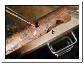 sure the whole of the spring will fit into the block and is therefore not spring
bound, if it was it would make the joint solid rather than sprung as designed.
Reassemble the parts us
sure the whole of the spring will fit into the block and is therefore not spring
bound, if it was it would make the joint solid rather than sprung as designed.
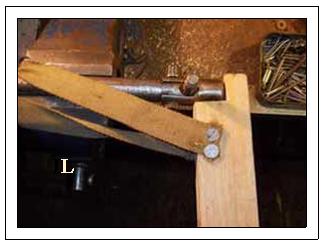
Reassemble the parts us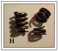 ing
my lever arrangement in (Pic. L) putting ‘copperslip’ anti-seize on the thrust
block sides and normal LM
ing
my lever arrangement in (Pic. L) putting ‘copperslip’ anti-seize on the thrust
block sides and normal LM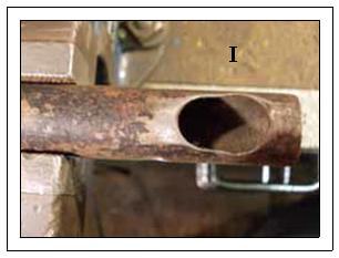 grease on the ball pin. Bolt up and secure with a new split pin. The second
scenario may be that when
you put the thrust block into the tube you find that the block is too short and
will be below the tube end, if this is the case put the spring in place and note
how much of the spring protrudes from the end of the ‘tube end’, if it is less
than 1/8”to 3/16” you will need
grease on the ball pin. Bolt up and secure with a new split pin. The second
scenario may be that when
you put the thrust block into the tube you find that the block is too short and
will be below the tube end, if this is the case put the spring in place and note
how much of the spring protrudes from the end of the ‘tube end’, if it is less
than 1/8”to 3/16” you will need
 to
put some packing into the
thrust block. I had to do this on the ones shown in this article as the spring
looked a little short, I used two flat washers in each block that were a perfect
diameter to fit inside (use Vaseline again to keep them in place). Check they
are not spring bound by pushing with the piece of wood or hammer shaft again,
but this time until it butts up to the ‘end of the tube’ rather than the thrust
block. Slide on the end cap with the chamfered thrust disc and some shims, using
the lever arrangement shown in (Pic. L) put pressure on the end cap as far as it
will go and add or remove shims until you get 1/32” ‘past’ the
hole before it goes solid. Finally remove clean up and reassemble with
‘copperslip’ on the thrust block sides and LM grease on the ball pin. Bolt up
and split pin. Greasing in service can only be done by pushing grease in the
joint with the finger whilst rotating the draglink by hand, leaving a good bead
around the joints to keep
water out. Or you could fit the later pattern with the g
to
put some packing into the
thrust block. I had to do this on the ones shown in this article as the spring
looked a little short, I used two flat washers in each block that were a perfect
diameter to fit inside (use Vaseline again to keep them in place). Check they
are not spring bound by pushing with the piece of wood or hammer shaft again,
but this time until it butts up to the ‘end of the tube’ rather than the thrust
block. Slide on the end cap with the chamfered thrust disc and some shims, using
the lever arrangement shown in (Pic. L) put pressure on the end cap as far as it
will go and add or remove shims until you get 1/32” ‘past’ the
hole before it goes solid. Finally remove clean up and reassemble with
‘copperslip’ on the thrust block sides and LM grease on the ball pin. Bolt up
and split pin. Greasing in service can only be done by pushing grease in the
joint with the finger whilst rotating the draglink by hand, leaving a good bead
around the joints to keep
water out. Or you could fit the later pattern with the g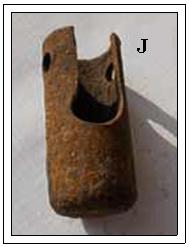 rease
nipples on each end. For most, has long as you grease regularly, you will not
need to do this again for a considerable mileage.
rease
nipples on each end. For most, has long as you grease regularly, you will not
need to do this again for a considerable mileage.
Ian Moorcraft (BA7C) with many thanks.