This is part two
WHEN
decarbonising, a sharp ground screwdriver or similar tool is suitable for
removing the carbon, all of which is scraped from inside the combustion
chamber in
the
cylinder head, from off the piston and valve tops, from round and inside the
valve pockets, the valve stem and the ports in the exhaust manifold.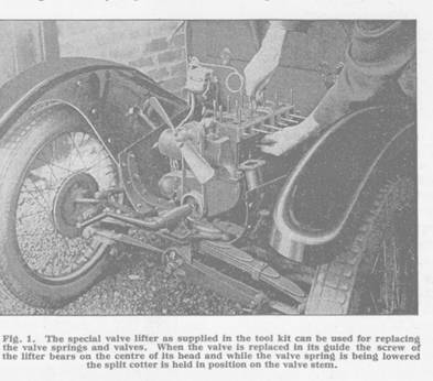
The cylinder head is left quite clean and smooth; care is needed to prevent carbon entering the water passages. Each piston is brought to the top of its stroke, level with the top of the cylinder block, for the carbon to be scraped off the crown. Two pistons will be up together, and into the two cylinders where the pistons are down, whether the centre two, or in turn the end two, it is desirable to stuff clean rag to prevent carbon dust intruding onto the cylinder walls. When two pistons have been carefully cleaned (without scoring the aluminium) the engine can be cranked over half a revolution to bring the other two level with the top of the block. While the valves are being cleaned they can be examined for signs of pitting on the seating face and, if the car has been in use for some time, for wear on the stems. Such wear would allow air leaks up the valve guide and bad seating of the valves to affect the running of the engine; and valves with badly-worn stems should be replaced by new. Another point that can be profitably examined for wear, if the car has been in use for a considerable period, is the top of each tappet screw which comes into contact with the bottom of the valve stem. After sustained usage this face may be worn hollow to allow extra clearance between the screw and the valve stem which the gauge cannot detect. This extra clearance would cause noisy running and the valves would open late and close too early. The remedy in the event of such wear is to fit a new screw. For convenient access to the tappet screws it is necessary to remove the valve springs and cups. A little difficulty may be experienced in doing this, for it is necessary to keep the top portion of the spring vertical while being pulled clear, so that it comes away without binding from the valve guide, while the bottom of the spring is pulled outward to clear the tappet. If the operator does not possess strong fingers the valve lifter can be used with advantage for this operation. With the screw slackened off the cupped portion of the lifter can be fitted under the spring. The spring cam then be compressed slightly and guided clear of the tappet and valve-guide by pulling the lifter upward and outward.
If the springs and cups are removed it is desirable to place them by their appropriate valves for correct reassembling.
To remove the
last vestiges of carbon, all the decarbonised parts are rubbed over with a rag
dipped in paraffin. The valve guides can be cleaned 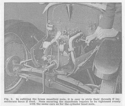 by
dipping the appropriate valve stem in paraffin, and moving it up and down, and
round in the guide.
by
dipping the appropriate valve stem in paraffin, and moving it up and down, and
round in the guide.
The plugs also require their share of attention. The plug can be dipped in paraffin and the carbon scraped or brushed from inside the main body and round the electrodes. Care is needed to avoid scratching or otherwise damaging the insulation of the central electrode, up inside. The plugs will probably require adjusting, the points most likely having burned wide. The gauge in the tool kit can be used for checking this adjustment which is effected by bending the outer electrode (or electrodes) towards the central electrode, so far as may be necessary. The thick blade of the sparking plug tappet clearance gauge is the one to use for testing the resulting gap.
The important point to remember when grinding-in the valves is that the job is not one to be hurried over. On the valves seating efficiently depends to a large degree the success of the work. Therefore it is wise to proceed about the attention deliberately and unhurriedly. Before grinding-in always slacken the tappet lock nuts, and screw down the tappet screws clear of the valve stems. If this is not done, the valve may be supported by the tappet before the grinding-in is completed, so preventing the pressure. necessary between the valve and its seating to complete the grinding-in.
On the head of each valve there is a number, which identifies the valve for its particular seating, the seatings being numbered from 1 to 8, starting from the front of the engine. It is very important to grind-in each valve only on its own seating.
The paste used for grinding-in is composed of carborundum powder and oil, as we have mentioned; it is obtainable in two grades, coarse and fine, for cutting and polishing respectively. A small quantity of the coarse paste is spread evenly around the seating face of the valve. A small helical coil spring, similar to the valve spring, about 8 in. in coil diameter by 11/2 to 2 inches long, is useful when grinding-in. When placed round the guide in the valve pocket, it lifts the valve off its seating every time the grinding-in pressure is relaxed. The valve is dropped in its guide over this spring.
If the
long-handled screwdriver, already mentioned, is used, its end is fitted in the
slot in the valve head. It is held by the top, and dropping his wrist, and
elbow, the operator presses the valve with a moderate pressure on to its
seating, where it is rotated backwards and forwards through a few degrees. After
a short interval the small spring is allowed to lift the valve off its seating,
when it is rotated round further, and the backward and forward movement
repeated. This is continued until the pitting is removed, the valve being
occasionally lifted clear, and the grinding paste wiped off the seating faces on
the valve, and in the cylinder
block, so that they can be examined to determine if sufficient grinding-in has
been given. The fine paste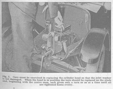
gives the final seating, using the same movement. If a brace is used for
grinding-in it is necessary to use the same reciprocating movement with the
occasional step advance to get a satisfactory result. To test the seating the
valve face is smeared with oil, and rotated several times while in position on
the seating, being pressed down the while with the same pressure as when
grinding-in. When, following this, the valve face is wiped clean and examined
in the light, it should reveal a bright polished ring all round. Although this
ring may not be continuous, so long as the ends (if it is broken), are
overlapping, though not in line, the seating is satisfactory.
The grinding-in paste being a cutting medium, would be very harmful were it left on the valves or in the guides. Consequently, after grinding-in all eight valves, it is important to clean away all traces of the compound. It is necessary to clean it from off the valve seats, the faces and stems of the valves, and from the guides. Paraffin (or petrol for that matter) applied on the valve stems as previously described, will clean the guides. Reassembling can then be begun.
If the valve springs and cups have been removed, the first operation is to replace them, each for its correct valve. Here, as for dismantling, the valve lifter can be used advantageously. The spring is pushed up round the bottom of the valve guide, and the cupped portion of the valve lifter is slipped under the valve cup, which is pushed into the bottom of the spring. The lifter is then pulled upward to compress the spring slightly, and the spring with the cup is pushed inward to slip over the tappet into position. It is necessary to ensure that the tappet is not being lifted by the cam when this is done, or the operation will not be so easy.
When this has
been effected with all eight springs, the valves can be replaced on their
correct seatings as indicated by their numbering, the stems being smeared with
grease or oil, so that the guides are lubricated. In refitting the split
cotters, the valve lifter is used in the same manner as when the cotters are
removed. The screw centres in the valve head, and the cupped end, fits under the
valve cup. By tightening the screw the spring is compressed to leave the bottom
end of the valve stem clear. Round this the two halves of the split cotter are
placed, the smaller diameter of the taper that they form being uppermost. They
are supported on the collar formed at the bottom of the stem, and will remain in
position if the stem is smeared with Vaseline. One-half is fitted first and is
moved round slightly behind the stem. The other half is then fitted, and both
are held to the stem while the valve lifter screw is slackened. As the valve cup
descends it is guided over the cotter, and when fully down the next valve can be
turned to. It is important to ensure that the valve cup is properly down over
the cotter otherwise one half will in all probability fly out and be lost.
Cranking the engine over to raise and lower the valve, will give an indication
of whether or not all is correct. At the first attempt refitting the cotters may
seem difficult, but it comes easier after the first few times. The fitting of
the cotters is facilitated if each has its top edge rounded off so that it will
enter the valve cup easily.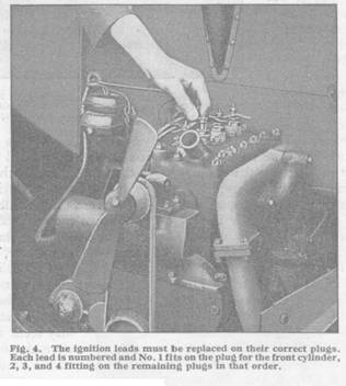
But much time and trouble can be saved if the split cotter pliers, advertised in THE AUSTIN MAGAZINE and mentioned in the first article, are used for refitting the cotters. The pliers being opened, each half of the split cotter is smeared with Vaseline and placed right way up in the recess in the end of each jaw. The pliers are then moved into position round the valve stem, and closed to hold the split cotter to the stem, just above the bottom collar. The valve cup is then lowered, as before, over the cotter. If a cotter, or half cotter, should fall behind the tappets, it can be removed in the manner already described.
When the valves are all refitted, it is convenient to check the adjustment of the tappets, or to readjust them if they have been lowered. The thin blade of the gauge is used to test the clearance between the valve stem and tappet screw. It is necessary to ensure that the valve is not being lifted when making this test, for then there is no clearance. If the tappets require adjusting, the small tappet adjusting spanner is used to turn the tappet screw to give the correct clearance from the valve stem. This can only be done when the locking nut is slackened. After the adjustment the locking nut is tightened down while the tappet screw is held from turning.
Before replacing the manifold and cylinder head it is advisable to ensure that the joint faces are clean and smooth, and new joint washers should be used where necessary to ensure tight joints. The cylinder head, with its joint washer copper side down and greased, is refitted over the studs, and the nuts with washers replaced. The nuts are tightened each a few turns only at a time, beginning with those at the centre and working to those at the ends. The exhaust manifold is replaced, the joint washer being lightly greased on both sides, and the three brass nuts are tightened home each a few turns at a time. With the joint washer between, the four bolts are inserted through the flanges of the manifold and exhaust pipe, and the nuts tightened as before. Too much force must not be used in tightening any of the manifold nuts, for being of brass the threads may be stripped.
The induction manifold with its washers can next be fitted, being secured by four brass nuts (for which the counsels of gradual tightening, and moderate force equally apply), and a set screw on the top, on which the steel packing washer for between the two manifolds is not omitted. The petrol pipe then can be connected up, likewise the throttle and air strangler controls, and the windscreen wiper tubing to the connection on the manifold. Before the sparking plugs are replaced a few drops of oil are injected into the cylinders on the piston tops to replace any oil that might have been removed from the cylinder walls by the rag that was used to prevent the intrusion of carbon. The sparking plugs are then refitted and screwed tight, each with its copper washer under, and the ignition leads are connected in their right order. They are numbered for the cylinders, 1 to 4, starting from the front. The horn is refitted on two of the cylinder block studs.
Replacing the radiator (if removed) and starting handle is a reversal of the dismantling operations. The radiator cowl, it must be noted, fits inside the curved front portion of the body.
With the cooling system refilled with water the engine can be run until it has reached its normal working temperature. The tappet clearance is then re-tested with the gauge and, if necessary, adjustments made as previously described. The valve cover with its washer then can be fitted. When the engine is running a little oil can be squirted round the base of each plug, when any leaks will be evident by the gases bubbling through. Such leaks are unimportant, but they can be remedied by tightening down the plugs, or fitting new copper washers under them.
When the decarbonising and grinding-in are completed, and the car leaves the garage, it will possess improved pulling powers at low speeds, without knocking early on hills; it will run cooler and the petrol consumption will be improved very considerably. The car, as we have said, will have regained in a considerable measure its youthful vim and vitality. There remains one more attention. After the first few miles following the decarbonisation the cylinder head, manifold and other nuts, bolts, and screws may be found to be slightly on the loose side. It is necessary to tighten home nearly all of them, with a turn or so of the spanner, after which they will remain secure.
This is part two