BUILDING A 6-VOLT ELECTRONIC REV COUNTER
Gordon Robertson 750MC Bulletin with many thanks
When building my 750 I decided for one reason and
another to drive the distributor off the front of the camshaft. All went well
until I came to thinking about the rev. counter. Then came the snag—where to
drive it from? The camshaft was otherwise engaged as was the crankshaft (in
supporting the distributor) and the dynamo was driven off the prop. shaft. The
obvious answer was to go electronic.
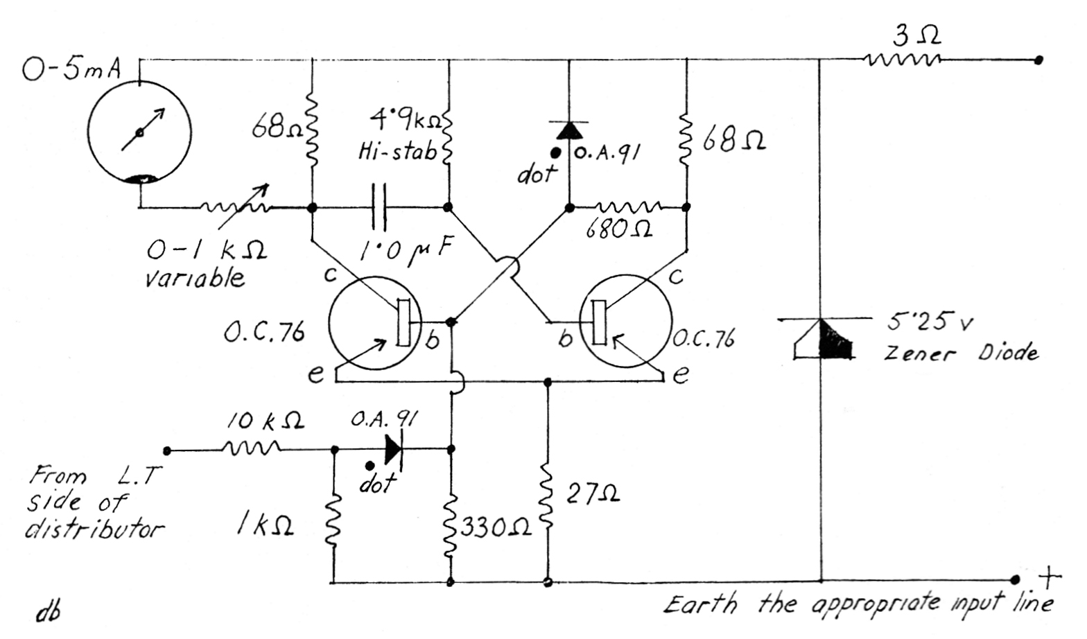
There follows the circuit which I ended up with, and which seems to work quite
well. Anyway, it has not blown up yet. For the more technically minded I will
start with a brief discussion of the principle.
The "little black box" contains a mono-stable transistor flip-flop circuit which
produces a fixed length square pulse every time it is triggered. The triggering
is provided from the 1.t. side of the distributor in a manner which I shall
discuss shortly, and the output pulses are fed to the milli-ammeter. Due to the
inertia of the meter only the average current is recorded, and since every pulse
is identical regardless of the triggering frequency (within reason, of course)
it is obvious that the current will be proportional to the triggering frequency,
hence to the engine speed. Moreover, the current is completely linear with the
triggering frequency, which is more than can be said for some systems.
The voltage on the LT terminal of the distributor has transient peaks of 100-400
volts, depending on the coil, every time the points open, and it is this peak
that we use to trigger the flip-flop. To cut the voltage down to a more
manageable value a potential divider is used, and since both positive and
negative peaks are present, we use a diode to eliminate the positive one. The
other diode is to ensure that the voltage does not rise too high and damage the
transistor. I also used a Zener diode to stabilize the power supply, but if you
do not wish to use it, its omission will do no more than allow the indicated
revs. to vary slightly with the battery voltage and who does more than to glance
at the rev. counter quickly anyway, so what the hell? If you do leave it out (it
costs about 7s. 6d.) you should also leave out the 3 ohm input resistor. I think
it should be used with a constant-voltage dynamo/cut-out or the meter will jump
every time the regulator operates.
The bits you will need are as follows and can all be
obtained in Tottenham Court Road.
1. The Meter. Any 0-5 milliammeter will do, but for 35s. from
Proops you can get a radio altimeter which is just such a meter and has a lovely
270° scale.
2. Transistors. Two Mullard O.C.76's
3. Zener diode, 5.25v. from Z. & I. Aero Services Ltd.,
Tottenham Court Road.
4. A 1.4 mfd. capacitor. Any sort except electrolytic as
these need a polarizing voltage and are not stable enough for the timing circuit
anyway. Paper tubular are O.K. and only costs a few pence.
5. Resistors. All ½ watt:-
1 Hi-stab between 4.9 and 5.4 Kohms.
1 3 ohm.
1 680 ohm.
1 330 ohm.
1 27 ohm.
1 1.0 Kohm.
1 10 Kohm.
2 68 ohm.
1 0.1 Kohm variable (miniature)
6. Diodes. Two Mullard 0.A.91.
7. Wire, solder, etc.
The circuit is quite straightforward and should present
no problems to the constructor, but there are a few tips which might be useful.
1. Remember the thing will have to operate under far from
ideal conditions, so make it strong.
2. Think carefully before trying any super-miniaturization.
It is very fiddly and you might easily get a dry joint. I know from experience!
My second model is in a 2in. x 4in. box on a bit of Tufnell sheet with holes for
the wires, etc. "Lectrokit" is ideal.
3 All lengths of wire should be insulated to avoid
shorting—remember the vibration. Also, it is not a bad idea to hold the
electronics in a piece of foam plastic or similar.
4 Be sure to get the diodes the right way round.
The Zener diode has its base towards the Positive side. The O.A.91's should have
the red dots as indicated on the diagram.
5. The transistors have a red dot on them too. The leads
go collector-base-emitter in that order, starting at the red dot.
6. I have already mentioned about the timing capacitor.
Avoid electrolytics, and use a good quality one. Likewise, the 4.9 K. resistor,
which should be a "Hi-stab" as these two control the length of the square pulse,
and hence the accuracy of the rev. counter.
NEGATIVE EARTH I have not tried the unit on negative earth, but the circuit will be exactly the same except that, of course, the negative side should be earthed and not the positive. The only other point is that the distributor will produce a positive pulse followed by a negative overshoot instead of vice versa. The positive pulse will be cut off by the diode, and it will be the negative overshoot that triggers the flip-flop. It may be that this negative overshoot will be too weak to do so, in which case you can try reducing the 10K. resistor in stages. Don't reduce it below about 2K. however, or you might overload the transistor if the circuit is at fault and not the potential divider after all.
We now come to the calibration. I did mine on a 'scope
with the aid of a pulse generator, but I think that it is unlikely that many
people would have such facilities. I think the best way would be to ask a friend
or acquaintance with a 6v. car and a rev. counter if you could hitch yours on to
his ignition system and calibrate it against his. Point out that there is no
conceivable danger to his car. Don't forget however to check the polarity of the
car. Alternatively, if you have an accurate speedometer you could work out the
revs. for a given speed in top gear, jack up the rear wheels and calibrate the
one against the other. The actual adjustment is done on the 0.1 K. variable
resistor, twiddling this until the correct reading is obtained.
There is not much to do in the way of trouble-shooting. If the meter shows
nothing at all, check the circuit and perhaps reduce the 10 K. resistor a bit.
Erratic readings generally indicate loose connections, and that is about all.
In conclusion I should say that mine works very well, but I have not given it any long-term testing, although there is no reason for it to stop working barring broken solder joints due to excess vibration.