BOSCH DISTRIBUTORS
ROTOR ARMS MODIFICATION
From another well-researched article by Terry Griffin(BA7C) with kind permission
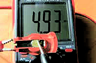
Due to German Ignition Suppression regulations all ignition equipment has to be fitted with suppression resistors—spark plugs, HT leads and rotor arm. It is the rotor arm that concerns us. Original Bosch rotor arms are fitted with a 5000 ohm/5K resistor which can fail, resulting in no sparks. Unfortunately, you cannot test it without an ohms meter or multimeter. If you try to do a continuity check with a test lamp, it will not light as the resistor will not pass the current, even if the rotor arm is OK.
Checking What You Have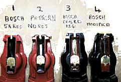
Non
-original or pattern rotor arms also vary as some are fitted with 5K/3K/2K or no resistor at all. They all look the same and come in red or black, so unless checked with a meter you cannot tell the difference. In the photo of the four rotor arms, No.2 has a continuous brass strip between the centre brush contact and rotor contact so we do not have a problem with this one. I have removed the insulation to show this, as it looks the same as No. 1. On the No3 arm, the resistor has failed, so there is no connection between the contacts – the insulation is removed to show the resistor. No. 4 has been modified to overcome this problem. Although a rotor arm is not an expensive part to replace, it is not an obvious part to change when trying to trace a misfire or ignition failure.By
-Passing The Resistor
 To
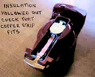
bypass the resistor, hollow out the insulation to expose the top of the
resistor. This can be done using a hot small soldering iron to melt it out, or a
small Dremel tool. Make sure the brass edges are clean as you will need to
solder a strip of copper or brass between the contacts.
To
bypass the resistor, hollow out the insulation to expose the top of the
resistor. This can be done using a hot small soldering iron to melt it out, or a
small Dremel tool. Make sure the brass edges are clean as you will need to
solder a strip of copper or brass between the contacts.
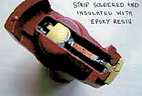
Bend the ends up as shown in the photo, so the strip sits on top of the resistor, solder each end then insulate with epoxy resin. This modification will eliminate any possibility of an electrical failure of the rotor arm.
Terry Griffin BA7C