THE BORG & BECK CLUTCH -
DISMANTLING & REASSEMBLING
This clutch is of the single disc dry type with the friction linings attached
to either side of the driven plate.
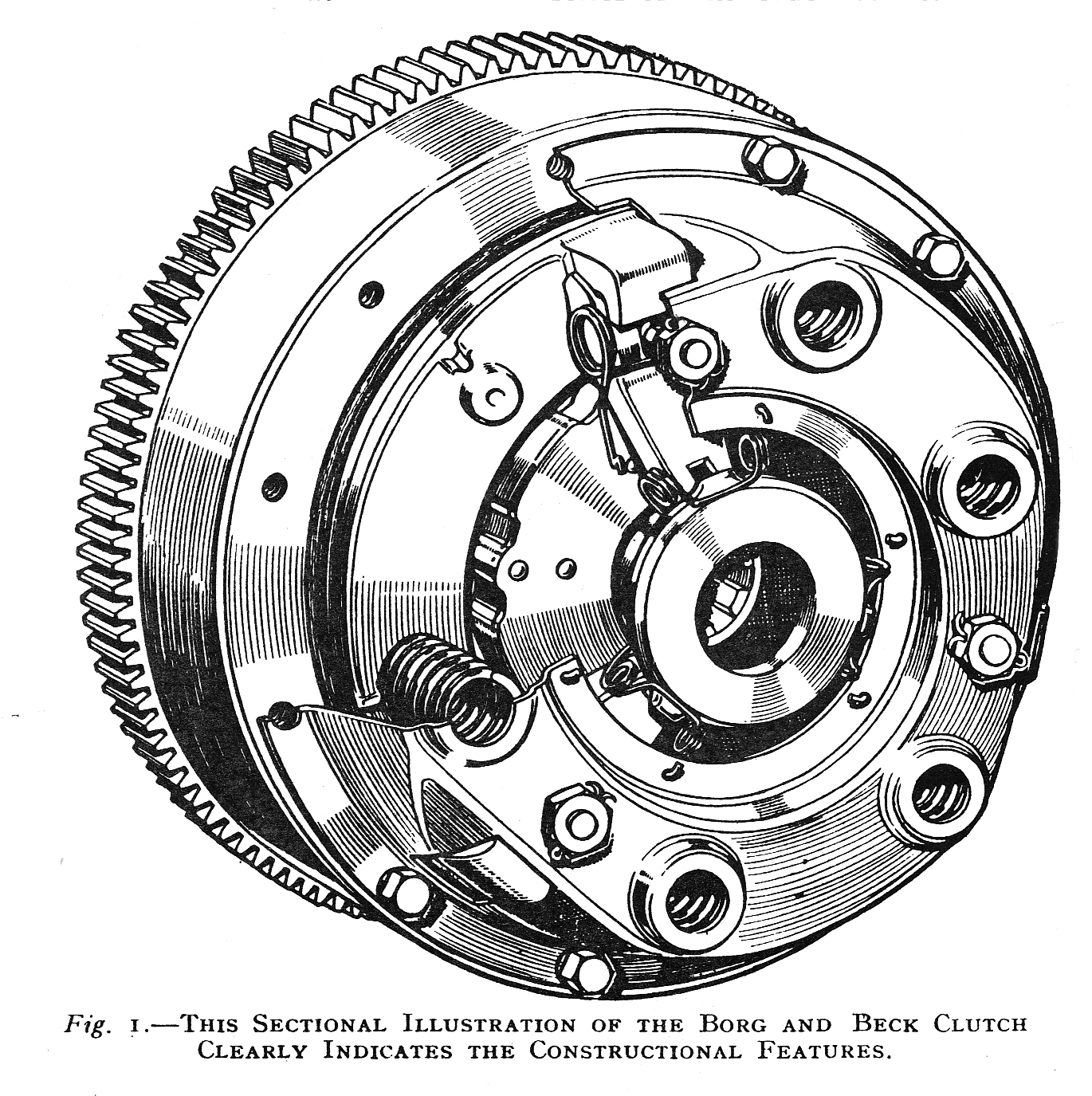 The
driven plate is located between the flywheel and the pressure plate, and the
actuating springs are situated between the pressure plate and the cover plate.
In the Borg and Beck clutch no provision is made for adjusting the spring
tension as the springs are of sufficient length to accommodate any wear which
may take place in the friction linings.
The
driven plate is located between the flywheel and the pressure plate, and the
actuating springs are situated between the pressure plate and the cover plate.
In the Borg and Beck clutch no provision is made for adjusting the spring
tension as the springs are of sufficient length to accommodate any wear which
may take place in the friction linings.
The clutch is released by three toggle levers mounted on eyebolts passing
through the cover plate. The clutch pedal pressure is applied to the inner ends
of the release levers by a circular plate located to the ends of the levers by
retaining springs, and the outer ends of these release levers bear against lugs
on the pressure plate by means of which it is withdrawn from contact with the
driven plate, the series of clutch springs being compressed in the process.
Naturally, as pressure on the clutch pedal is removed, the clutch springs again
force the pressure plate into contact with the driven plate, and connection
between the engine and transmission is again established.
The Action of Wear.
Consideration will show that wear of the clutch linings will permit the
pressure plate to take up a position closer to the flywheel and that the release
lever inner ends will in consequence move rearwards so as to bring the lever
circular withdrawal plate closer to the thrust bearing of the withdrawal
mechanism and eventually actually make contact with it. When this happens, the
clutch cannot be fully engaged and clutch slip takes place, accompanied by
excessive wear of the friction surfaces and withdrawal mechanism, as explained
at greater length in the general section on clutches.
Adjustment.
Maintenance of an adequate clearance between the thrust bearing and the
release lever ring is therefore most important in connection with the Borg and
Beck clutch and is, indeed, the only service adjustment provided.
The correct clearance between the face of the release lever plate and the thrust
bearing face when the clutch is in the engaged position is 1/16 in., and the
correctness of this adjustment should be checked at reasonably frequent
intervals, say every 5,000 miles.
Adjustment for this clearance is always provided in the clutch pedal mechanism,
and since the design of this varies on different makes of cars employing this
clutch, you are referred for particulars of adjustment to the section dealing
with each individual make.
A factory adjustment is provided for the release levers at their fulcrum
eyebolts to enable them to be set so that they all take an equal share of the
withdrawal load. This adjustment is carried out by the nuts attaching the
eyebolts to the cover plate, and has been carefully made at the works before
delivery so that attention at this point is not required. The nut is therefore
locked in position by a split pin.
In order to ensure correct action of the clutch, replacement of the levers
should be made in sets and not individually. Fresh replacement sets correctly
adjusted can be obtained from the makers.
Removing Clutch Assembly.
Access to the clutch assembly is achieved by removing the gearbox and
clutch housing from the chassis, thus exposing the clutch on the face of the
flywheel. Care must be taken when removing the gearbox to avoid leaving it
hanging by its primary drive shaft without adequate support when the attachment
bolts are removed, for this will place a heavy load on the clutch plate centre
which will almost invariably result in damage.
The clutch assembly is released from the flywheel by withdrawing the series of
screws attaching the cover plate to the flywheel. These screws should be
withdrawn with care a turn at a time until the spring pressure is released, in
order to avoid buckling the cover plate. After a few turns the spring pressure
will be taken by the release levers, and the cover plate screws can then be
withdrawn completely, enabling, the clutch assembly to be removed from the
flywheel.
Removal of the cover plate assembly will be facilitated by the insertion of
wedge pieces, approximately ¼ in. thick, 3/8 in.
wide, and 1 in. long, between the cover plate and the inner ends of the toggle
levers to restrain their movement. Removal of the cover
plate assembly completely releases the clutch plate.
Dismantling the Cover Plate Assembly.
If further dismantling is found necessary in order to replace components of
the cover assembly, the use of a drill press or arbor press is advisable,
although a compressing tool can often be devised from scrap material usually
found in a garage.
It a suitable press is available the cover assembly should be placed on the bed
with the pressure plate downwards and resting on blocks of wood so as to give
plenty of clearance between the flange of the cover plate and the bed of the
press and avoid damage to the ground face of the pressure plate.
Now place a metal bar or block of wood across the top of the cover plate so that
it rests on top of the clutch spring bosses, clear of the eyebolt nuts, and
apply pressure to the bar with the ram of the press so as to compress, the
clutch springs.
When the cover plate has been forced down sufficiently to free the release
levers from load, the eyebolt nuts may be unscrewed after withdrawing their
split pins. The pressure on the cover plate can then be released slowly,
permitting the clutch springs to extend gradually without flying out, and the
cover plate to be removed.
This enables all the component parts to be inspected, and it is advisable to
replace any that show signs of undue wear.
Special Carbon Graphite Rlease Bearing.
It should be noted that the majority of Borg and Beck clutch
applications utilise a special type of carbon graphite bearing, made up in the
form of a ring, for the purposes of taking the load when the clutch is released.
This carbon ring is housed in a suitable cup with trunnions formed on it and
attached to the throwout forks of the clutch-pedal mechanism.
This special-type release bearing has an extraordinary long life and requires no
lubrication or attention in the usual way, but it is as well to examine it
when the gearbox is removed and if it shows signs of undue wear it should be
replaced by a new carbon ring. The carbon ring can easily be removed from its
housing by loosening the pinch bolt provided. When the new ring is inserted,
care must be taken not to unduly tighten the pinch bolt, otherwise a crack or
fracture will result, causing trouble in service.
Reassembly of Cover Plate Components.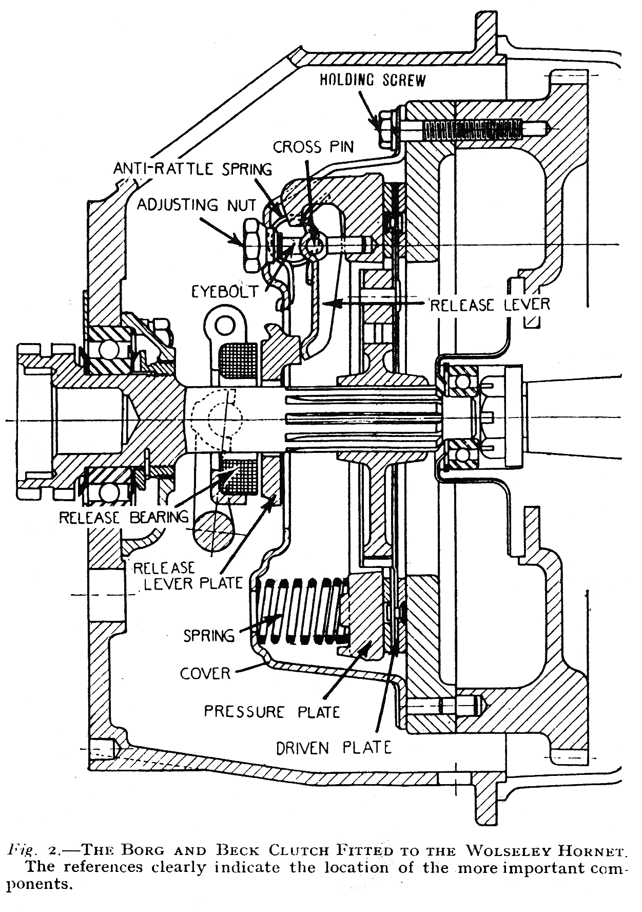
In the first place, it is necessary to rest the pressure plate on
wooden blocks on the bed of the drill press as described for dismantling, and to
place the series of clutch springs in place on their bosses on the back of the
pressure plate.
The release levers can then be reassembled on the cross pins of the eyebolts
and the ends of the eyebolts introduced into their guide holes in the pressure
plate, taking care to see that the short end of each release lever is in proper
engagement with the underside of the hooked lugs of the pressure plate. It is
advisable to apply a small quantity of graphite grease or graphite moistened
with oil to the short end of the release levers and to the cross pins of the
eyebolts, in order to assist the clutch action.
If the original parts are replaced, care should be taken to see that they are
reassembled in their correct relative positions in order to maintain the
balance and adjustment of the assembly. The adjusting nuts, eyebolts, pressure
plate lugs, and cover plate are all stamped with identification numbers to
facilitate this.
The cover may now be laid in position on top of the clutch springs, taking care
that the anti-rattle springs for the toggle levers are correctly positioned and
that the tops of the clutch springs are properly located in their embossed seats
in the cover plate.
The bar or wood block may now be placed across the cover plate and pressure
applied to it so as to compress slowly the clutch springs, taking care that the
cover plate does not foul the ends of the eyebolts or pressure plate lugs, which
should carefully be guided through their respective holes in the cover plate.
Care must also be taken to see that the springs remain in position on their
seats during the compressing process.
Retaining the cover plate in the compressed position, the eyebolt retaining
nuts may be screwed on to the stems of the eyebolts until the split pin holes
register. The split pins may now be inserted and the nuts locked to the
eyebolts.
See that the eyebolts and release levers are in their correct positions and
carefully release the load from the cover plate. This will enable the release
lever plate to be placed in position on the inner ends of the release levers,
and fastened thereto by the series of retaining springs, care being taken to see
that the ends of the toggle levers are engaging the projections on the release
lever plate properly.
Replacing Cover Plate Assembly on Flywheel.
When replacing the cover plate assembly on the flywheel it is necessary
to correctly position the driven plate first, or the gearbox primary shaft
cannot be inserted into the spigot bearing in the centre of the flywheel.
To do this a dummy clutch shaft must be employed to locate the clutch plate
during assembly, or, failing this, the primary or clutch shaft must be withdrawn
from the gearbox and used for the purpose.
Pass the dummy clutch shaft through the hub of the clutch plate entering it from
the chamfered end of the plate hub, or gearbox side, so that the chamfers are on
the outside when the end of the dummy shaft is inserted into the flywheel spigot
bearing.
When the clutch plate and dummy shaft are properly located on the face of the
flywheel the cover plate assembly may be placed in position and the cover plate
retaining screws replaced finger-tight. The use of wedge pieces under the toggle
levers, as on dismantling, will assist this. Now tighten up the cover plate
screws in rotation a turn at a time until they are all quite tight. Taking care
to see that the wedge pieces do not fall into the cover plate.
The dummy clutch shaft may now be withdrawn and the gearbox assembly replaced.
If the gearbox primary shaft is withdrawn for the purpose of assembling the
clutch, it is necessary to pass it through the cover-plate assembly first before
introducing it into the clutch plate hub or it will not be found possible to
place the cover-plate assembly in position, as the hole in the release lever
plate is not large enough to pass over the primary drive gear on the end of the
shaft.
Relining the Clutch Plate.
The clutch plate on the Borg and Beck clutches is lined with a special
type of friction disc, and this is attached to alternate segments of the plate
on each side with special rivets. The correct relining of these plates cannot be
carried out by the normal garage, and the plates should be sent to the makers
for relining attention.