From an article in the Austin Seven owners Club
I have a
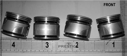
reconditioned block and new pistons ready to fit but decided I must find out why
the pistons removed from the old block had worn as they had. There was also a
certain amount of abrasive (scuffing) wear. The wear patterns shown on pistons
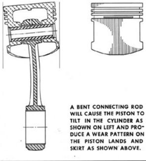
1, 2 and 4 are those associated with having a bent connecting rod. N.B. The
angles of the pistons, as they would have been in the cylinder, have been
exaggerated! In no way could I use the existing rods for the rebuild without
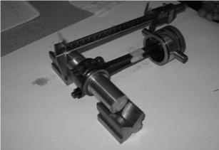
first checking them out. Initially I decided to use a two-mandrel approach and
am grateful to John Peach for machining up a special mandrel to fit the big
ends.
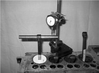
Checks were made across the mandrels using a vernier calliper, with a digital readout, and the readings confirmed that the rods were indeed out of alignment. The next step was to check the 'as assembled' alignment. The crankcase/block interface surface was lightly lapped so that it could be used as the datum for subsequent measurements. The crankshaft was then located in the crankcase using dummy 'plain' bearings, lent to me by Mike Hutton. The connecting rods were then fitted and a silver steel mandrel inserted into the little end. To clamp it tight, it had a recess to mirror that on the gudgeon pin, This time a dial gauge, borrowed from Jack Allen, was used to check the alignment of the 'mandrel' over a distance of 4 inches, 2 inches either side of the rod centreline. This again confirmed that the rods were out of alignment. The readings I obtained were as follows, No. 1 rod - 0.015 in., No. 2 rod - 0.006 in, No. 3 rod - 0.003 in, No 4 rod - 0.021 in. Not good news!
In practice it is
accepted that, over a length of 4 inches, the out-of-alignment should not exceed
0.002 inches. In the late '80s I had had the crank re-ground and the rods
re-metalled by a well known 'Red Book' supplier. Perhaps I was too trusting in
assuming that everything
 would
be geometrically correct, so I fitted them as received. Quite clearly they were
not. However, to have 3 'bent' rods is, surely, a most unusual occurrence. I am
of the opinion that the boring tool used to clean out the white metal bearings
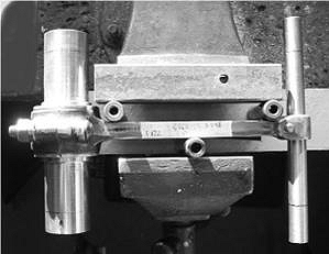
could well have been incorrectly aligned. I have now corrected the misalignment
by cold bending the rods in a vice. See photos opposite. I do have an older
crankshaft and rods in reasonable used condition so I decided, out of interest,
to check the alignment of each rod in the assembled state. The readings obtained
over 4 inches were as follows, No. 1 rod - 0.001 in., No. 2 rod - 0.003 in, No.
3 rod - 0.001 in, No 4 rod - 0.001 in. - a very acceptable set of
readings. This is really what I would have expected of the rods that I fitted
originally.
would
be geometrically correct, so I fitted them as received. Quite clearly they were
not. However, to have 3 'bent' rods is, surely, a most unusual occurrence. I am
of the opinion that the boring tool used to clean out the white metal bearings
could well have been incorrectly aligned. I have now corrected the misalignment
by cold bending the rods in a vice. See photos opposite. I do have an older
crankshaft and rods in reasonable used condition so I decided, out of interest,
to check the alignment of each rod in the assembled state. The readings obtained
over 4 inches were as follows, No. 1 rod - 0.001 in., No. 2 rod - 0.003 in, No.
3 rod - 0.001 in, No 4 rod - 0.001 in. - a very acceptable set of
readings. This is really what I would have expected of the rods that I fitted
originally.
Nigel Offer
with many thanks.