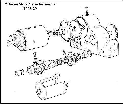
The geared starter motor was fitted to Austin Sevens up to late 1929, and then changed to direct drive at the same time that the gearbox lost its gate. I am not sure how the bacon-slicer epithet originated, but the unique thing about the BS is the fact that the motor drives the bendix through a pair of spur gears. One effect of this is the unmistakable growl that the device produces.

The Motor
The motor is a fairly conventional four-pole series-wound unit. This means that the brushes are connected in series with the field coils across the supply. Series motors give a very high torque at low speeds, which is just what we need. Shunt-wound motors, where the field is connected across the supply, do not, but their speed is more constant. They tend to be used for wiper and heater motors on moderns.
It may be worthwhile digressing to the theory behind all this. Readers who are yawning already please skip this section....
A Bit of Theory
A DC motor works by passing current via the brushes to the armature windings, thus magnetising them. This reacts with the stationary field poles, causing a turning moment on the armature, so that the next pair of commutator segments come under the brushes, and a different set of coils are energised. Ergo, rotation. As the armature rotates, it also generates current, like a dynamo, which opposes that fed to it. This back EMF as it is called, causes the current consumption to decrease as the speed increases. As, in a series-wound motor, all the current passes through the field, the field weakens and the motor speeds up. If we apply a load, the motor slows down, the back-EMF increases, the current increases, and with it the torque, and the increase in the field strength slows the motor more. In a shunt motor, the field flux is constant, so the speed varies less with load. Indeed, the speed increase off-load on some larger series motors is quite dramatic; the average vacuum cleaner motor run without its fans will self-destruct as it gets to 80,000 or so rpm, unlike the RB-211. Don't try this without your parents’ permission! The off-load speed of a starter motor is something like 1200 rpm; in use it varies between 100 and 600 rpm, depending on temperature, engine oil viscosity and compression, or lack of same.
The Bendix
In the twenties, it seemed, manufacturers thought that the starter Bendix should be nearly as large as the engine. This one certainly fills the bill. To remind you of how the bendix works, the engine idles at something like 400 rpm, but only needs to be turned over at 80 or so rpm to start. When current is supplied to the starter motor, the counterweight on the pinion makes it lag behind. This causes it to screw itself (sorry) along the quick-thread on the sleeve and crash into engagement with the teeth on the ring-gear, turning the engine. When the engine fires, it speeds up, so the pinion is thrown back along the quick-thread. The sleeve is connected to the shaft with an enormous spring to cushion the blow as the pinion is flung back and forth. "C'est brutale, mais ce marche" (Ettore Bugatti, I think). A tiny pin and spring keep the pinion out of the way as the car is being driven - more about that little fellow later. The slotted loose end on the sleeve seems to have no useful purpose at all, as far as I can see.
Dismantling and Repair

Starter motors are inherently fairly reliable things, mainly due to the fact that they spend most of their lives not running. Disconnect the lead and remove two bolts. There should be a dowel in the crankcase top. Remove the front plate. Before removing the motor, it is an idea to slacken the large nut holding the gear on the end of the armature shaft, temporarily locking the gears with a piece of alloy or brass jammed in the teeth. Disconnect the lead on top of the motor, then unscrew the bolt on top of the casting, and the motor should pull out rearwards. If not, warm the casting with a hot-air gun or fan heater. As a last resort, hit the gear with a wooden mallet. When the motor is out, remove the gear and retain the woodruff key. Remove the band around the brush gear, disconnect the lead to the positive brush, and that to the large terminal, and take out the two long bolts. The motor should come apart completely. Do not lose the washers (one at each end of the armature shaft.) Wash all the parts off and examine them. I find that it is a good idea to put all the small screws, bolts etc. in a screw top jar with some petrol, and wash them thus. When dry, spray them with WD40, which leaves a film of oil on them. The motor bearings are bronze bushes that are perforated to hold grease, and wear slowly. The only other wearing parts are the brushes and commutator. The latter should be undercut slightly, according to a piece of period literature. Use a piece of hacksaw blade with the set ground off and finally clean the commutator with glass paper or wet-and-dry. Do NOT use emery as this leaves particles embedded in the copper. The commutator, if badly worn, should be skimmed in a lathe and then undercut as above.
Examine the field coils, and the connections between them. The tape tends to fall off these and they short to the bolts giving off much smoke. Re-tape with half-inch tape from a haberdasher and paint with thick shellac or even liquid resin. Insulation tape is a total waste of time here. It is not a bad idea to sleeve the through bolts with insulated sleeving; the outer sheath of TV aerial cable is about the size. Renew the bushes if worn, as they can wear down until the brush holders score the commutators badly.
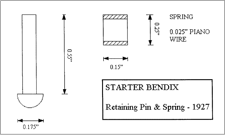
Now for the Bendix. Take out the three bolts holding the cover on, and remove the cover. Bend back the lock-tab on the outer bolt and remove it. The collar will then slide off; watch out for the woodruff key. After removing the key, the remainder of the Bendix can be removed and dismantled, including the gear and shaft. When sliding the pinion off, the retaining pin and spring will tend to fly out. Problems with the Bendix are few - the most common ones are due to incorrect reassembly (see below) Also, the retaining pin and spring tend to get lost, and be replaced with all sorts of bits, if at all. The two bolts holding the spring tend to work - loose with monotonous regularity; the lock-tabs are really insufficient. I have found that the best way to prevent this is to use Loctite on the threads and drill the heads for wiring. I have given a drawing for the retaining pin and its spring. It slides in a bronze bush in the web of the pinion. The spring length is critical: too long and the starter will not engage, too short and the tension will be insufficient to keep the pinion in the parked position. The switch may be the original, or a replacement item from a forklift truck. The original switch can be overhauled. Common problems are wear where the shaft goes through the cover plate and pitted contacts. The contacts can be cleaned up with a file and the moving contact re-tensioned. The cover plate can be bushed by those with access to a lathe. Some of the insulation here, and elsewhere, is made from thin flexible fibre sheet known as Presspahn. There is a material known as Elephant Hide available for this type of job now. There should be two tufnol washers where the contact bolts pass through the casing, and the smaller tufnol disc goes inside, after the cylindrical piece of fibre. There should be a piece of fibre between the terminal nuts.
Re-assembly
Grease all the bushes with moly or graphite grease. Assemble the motor, not forgetting a washer on each end of the armature shaft and to hold the brush-holders back from the commutator. It is easier to put the shaft in the commutator endplate first, then put the body and drive end plate on. Both endplates locate on pegs, so cannot be put on wrong. If you are sleeving the bolts as described above, put the sleeves on before the drive endplate. Tighten the bolts, and replace the bushes and brush lead. The band can be put on now. It should have a strip of fibre insulation material riveted to it. The ends of the inner band go below the retaining plate, the rolled ends clip over it. You can test the motor on a battery, now. Put the pinion with its retaining pin and spring on to the threaded sleeve. Do not lubricate the thread. Screw the slotted nut on the end, preferably with Loctite instead of staking the sleeve into the slots of the nut, as was done originally. Grease the bush in the casting and put the Bendix shaft in, after placing the radiused washer on it first. If anyone has the old Platts catalogue, the two washers are shown in the wrong places. The other washer goes on next, followed by the pinion/sleeve assembly, the spring key and collar. Take care that the bolts holding the spring are put in the right way round; the one with the spigot goes in the collar and a blind hole in the shaft. Renew the bolts if the threads are worn. Use Loctite and/or wire as detailed above. Grease the bush in the cover and replace it. Put motor back in place and replace the retaining bolt. Assemble the gear with its key. The larger boss on the gear faces forward, i.e. away from the motor. Wedge the gears and tighten the nut - use Loctite here. Replace the switch and re-connect the leads. The lead on top of the motor should have a little cover on it. If missing, a replacement can be made from the case of a marker pen. It should be lined with elephant hide.
Your starter should perform perfectly now. A note for 12 volt buffs - no alterations seem to be needed to the starter motor . There is nothing like 12 volts to awaken your mag-engined Seven from its winter slumbers. Remember not to switch the dynamo on when starting from 12 volts - it will burn out when the cut-out closes, and not to do it at all on a coil engine.