Back-to Basics—The A7 Clutch
A member of our club recently asked me how the clutch on the A7 works, which prompted me to try to describe the operation of the clutch.
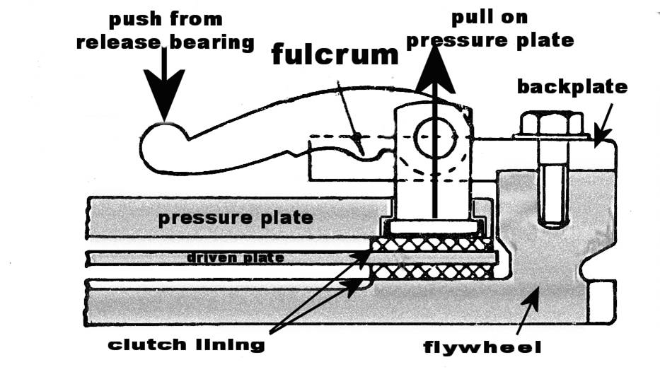
With reference to the diagrams opposite you will see there are 4
large components: the flywheel, the back plate or flywheel cover; the pressure
plate; and the clutch (driven) plate, which is connected to the gearbox by a
splined shaft. All but the latest Austin 7 clutches had the friction material
riveted to the flywheel and the pressure plate.
You will see that between the back plate and the pressure plate there are several coil springs (only one is shown for clarity but there are actually 12). When the back plate is bolted to the flywheel these springs press the pressure plate towards the flywheel pinching the driven plate between the flywheel and the pressure plate. Hence when the flywheel rotates, the whole assembly goes around as one driving the input shaft on the gearbox.
To enable us to engage a gear when the engine is running we must disengage the clutch driven plate, which is connected to the gearbox from the flywheel. This is done by moving the pressure plate towards the back plate thereby compressing the clutch springs.
To achieve this, firstly imagine a basic seesaw made out of a
plank and a round log (fulcrum), a large child at one end and a small child on
the other end. To achieve a balance the large child will be positioned near the
log and the small child further away from the log so the plank is the toggle.
When the clutch pedal is depressed the clutch actuating assembly moves forward
pressing on the toggle finger. This is the end equivalent to the end the
lighter child is sitting on the see-saw. The fulcrum is close to the other end
of the toggle and rests on the back plate. When the clutch is assembled the
clutch withdrawal pin is inserted through the pressure plate and the back plate.
The pin cannot pass right through the pressure plate because the flange sits in
a recess in the pressure plate. Having been passed through both plates the
toggle is attached to it by a pin. When the toggle is moved by the clutch pedal
it tries to pull the clutch withdrawal pin further through the back plate.
In doing so it pulls the pressure plate towards the back plate compressing the
clutch springs and relieving the pressure on the driven plate allowing it to
rotate freely at a different speed to the engine or, in fact, stop rotating
altogether if a gear is engaged and the vehicle is stationa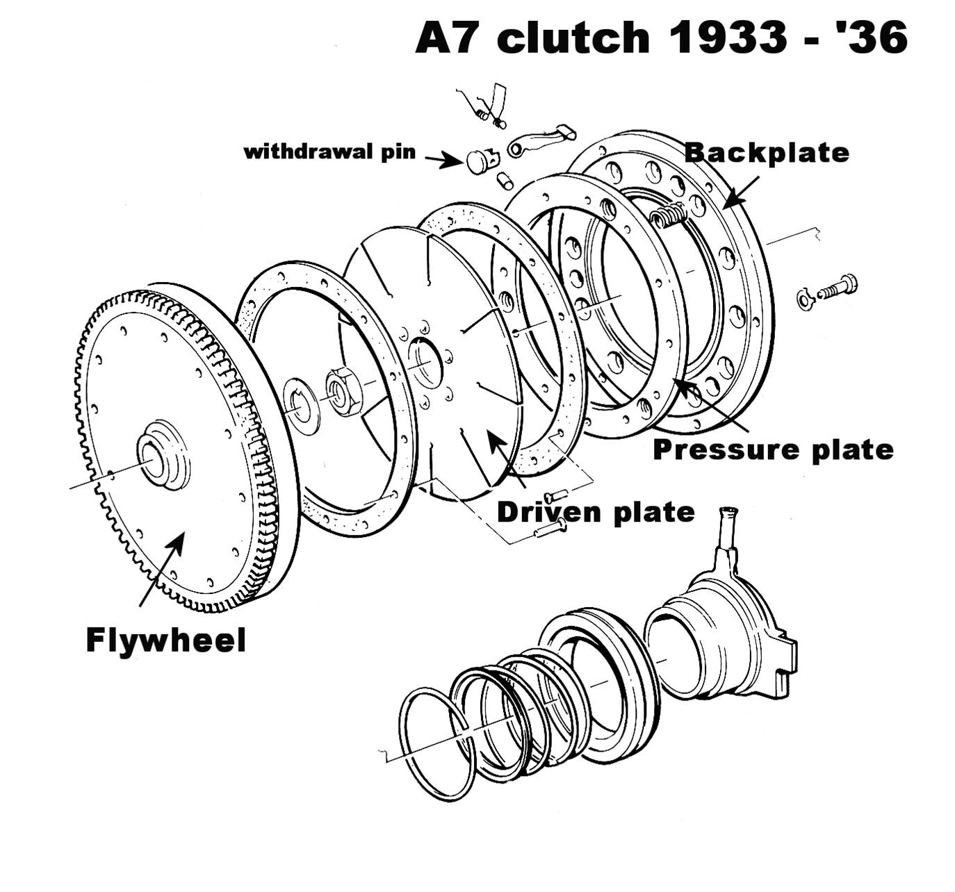 ry.
ry.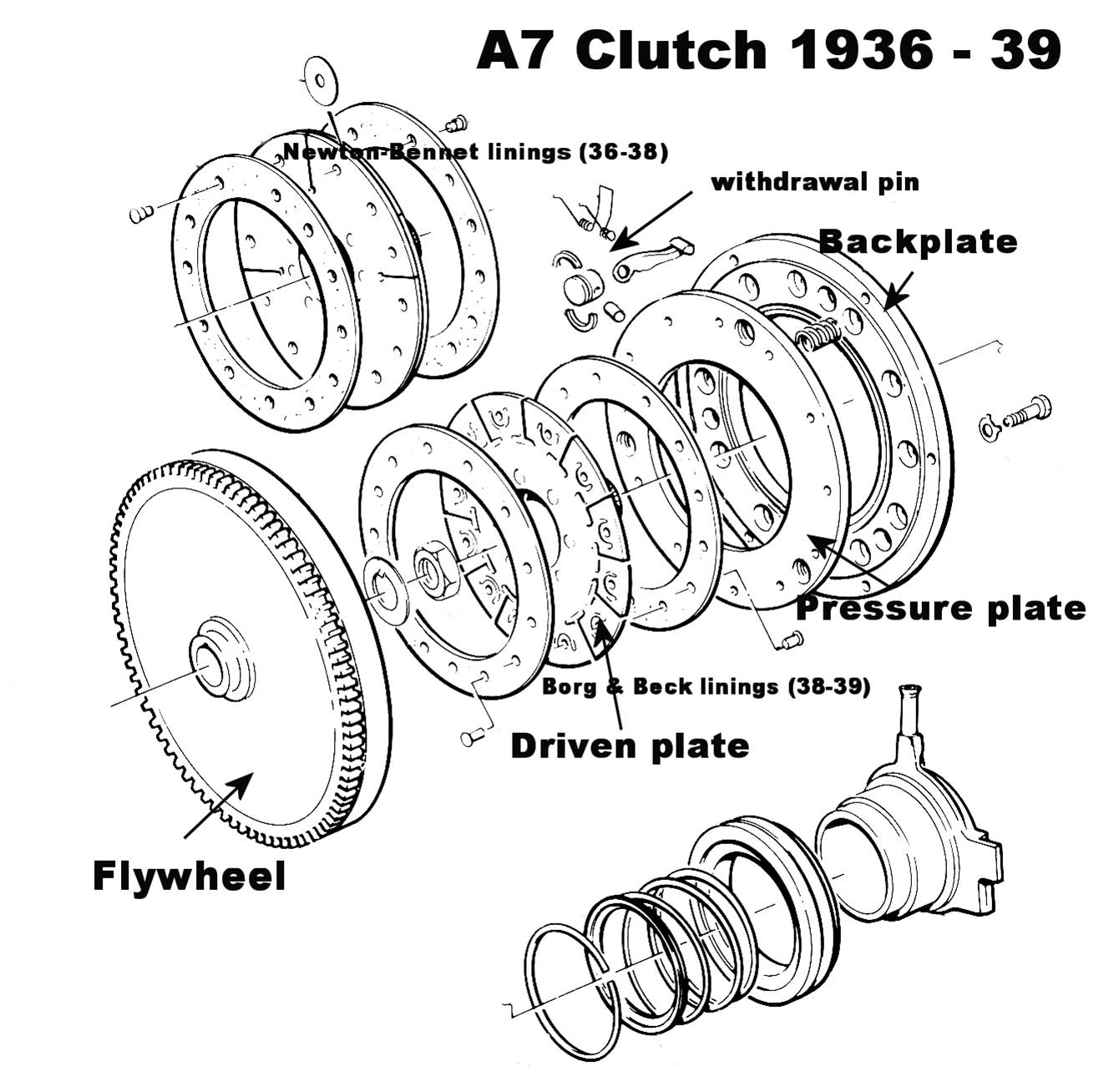
You will observe that, as the clutch pedal is released, friction occurs between the flywheel and the driven plate to enable the vehicle to move off from a stationary position without a jerk. If, however, this friction is allowed to continue as some people are apt to do by holding a vehicle on a hill in a stationary position by slipping the clutch rather than applying the brake, friction produces heat and wear, so the clutch linings will be worn away and the whole clutch assembly will heat up. If this situation continues the heat build up could take the temper out of the clutch springs, which will allow the clutch to slip, as the spring pressure will be less.
Roger Ballard
DIFFERENCES IN A7 CLUTCHES
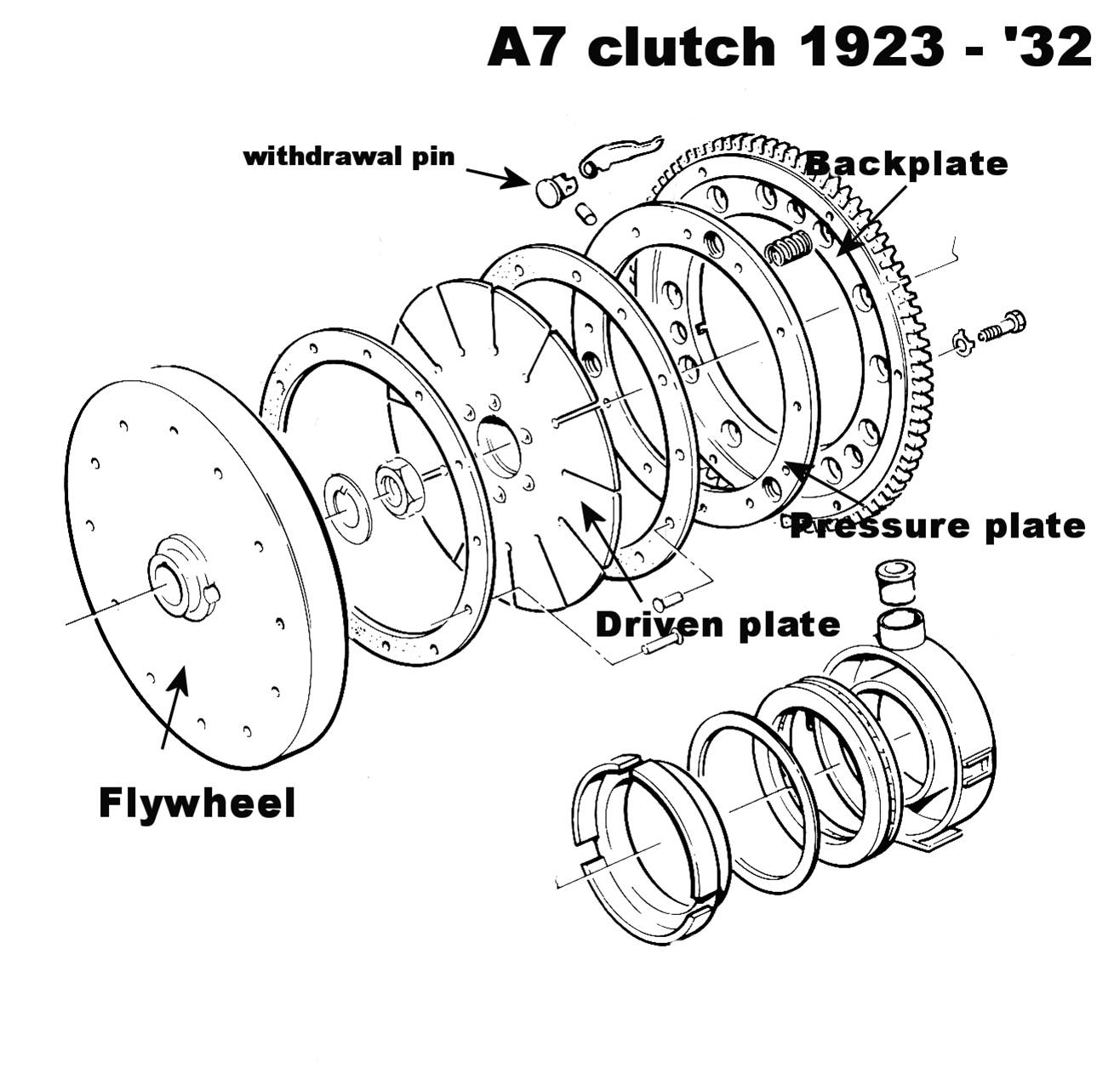
Over the years there have been four versions of the A7 clutch—the early “bacon-slicer” with the starter ring on the back plate instead of on the flywheel and the starter motor inside the cab; the later, but similar, clutch having the ring gear on the flywheel and the starter motor on the engine side; and the later, Ruby-type clutch with the friction plates riveted to the centre plate with its two versions: Newton-Bennet 1936-38 and Borg & Beck 1938-39.(See additional notes below) In the first two early versions the friction plates are riveted to the flywheel and back plate. There are also two versions of the oiler and thrust bearings.(See additional notes below)
Also note that the later clutch withdrawal pin has a groove and 2 collars to form the brim of the top hat shape similar to the cotter pins on a valve stem allowing the pins to be fitted from the rear of the clutch assembly.
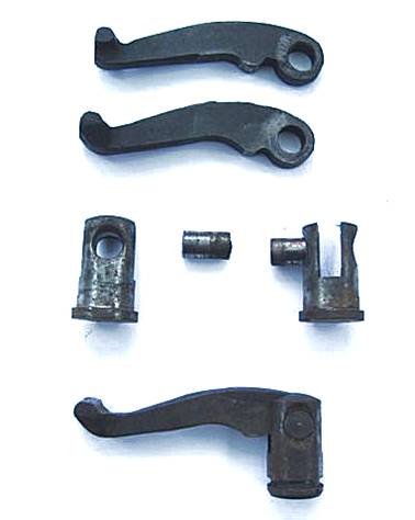
Clutch levers also come in slightly different shapes: although The Seven Workshop stock only one type (1933-39 part no 0155) Austin originally quoted different part numbers for 1933-36 (1A3130) and 1936-39 (1A3241) so Austin must have changed the design of the clutch lever for the later clutch assemblies.
AN ADDITIONAL NOTE ABOUT CLUTCH LEVERS
Following last month’s article from Roger about the basic working of the clutch and the rôle of the infamous clutch lever or toggle, members asked for a little more clarification on how the lever actually pulls the clutch apart. Well, as they say, a picture is worth a thousand words so, hopefully, the accompanying diagram will reveal all!
Roger wishes to underline the fact that there are, indeed, two slightly different types of levers available from the Seven Workshop:
“Flat section for 3-speed gearboxes 1923-32 (part no. 0154) and
T-section for 4-speed gearboxes 1933-39 (part number 0155)”
So make sure you order the right ones! David
AN ADDITIONAL NOTE ABOUT CLUTCH RELEASE BEARINGS
One of the most
unreliable aspects of the 3 speed gearbox cars is the slotted-collar clutch
thrust bearing. The clutch levers have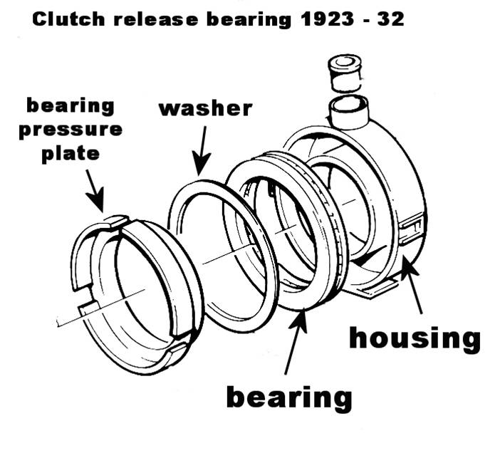 a nasty habit of wearing through the collar at the most awkward of moments,
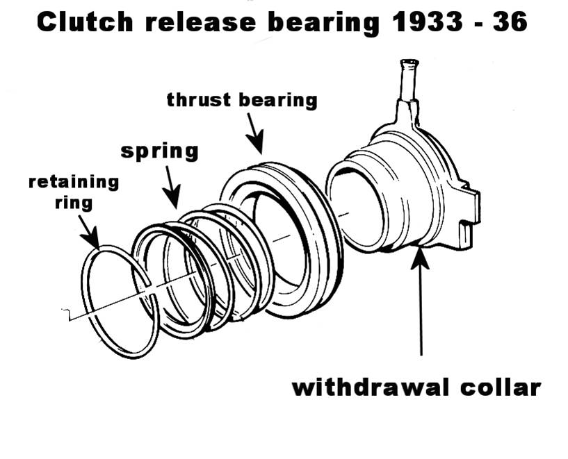 necessitating removal of the engine to restore the mess.
Instead of re-cutting 3 new slots, a far more reliable alternative is to fit a 4 speed gearbox type clutch thrust, which simply slides on in its place. When the gearbox is bolted up to the engine, make sure there is clearance between the race and the levers and when the pedal is depressed the clutch disengages fully. If not, bend the 3 levers with a long pipe accordingly*. Once bent make sure all 3 are exactly the same distance from the centre plate to avoid premature wear and judder.
The clutch pedal rod spring can now be dispensed with as there is no need to keep the race in constant contact with the levers as there was before; mouse trap springs need not be fitted; nor the 4-speed clutch race return spring, but, if preferred, the later wide foot clutch levers may be used.
The above simple and unseen modification should result in a more reliable set up and a smoother clutch operation. Mine has been fitted for about 40,000 miles, so far without any problems.
*If you use late levers you will have to heat them cherry red before bending as I believe they are cast. Of course there are other methods of adjusting the levers if you so wish but Munwellyns and now GM Auto Services always heat and bend all. Some people prefer to fit mouse trap springs, (not easy), but Glyn and I have never found it necessary. Gary Munn
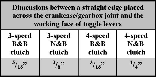
B&B = Borg & Beck;
N&B = Newton Bennett