There is a great deal of uncertainty about when coloured cables were introduced in the motor industry although it is fairly certain that individual cable tracing became necessary with the introduction of wiring looms (harnesses) which were prefabricated by specialist companies and supplied to the car maker for installation during building. In 1966 the three companies who produced wiring looms gave evidence to a Parliamentary enquiry into possible `price fixing` in the trade, their submissions form the only credible industry information about the early wiring practices. In their evidence the companies stated “.... it is not certain when the prefabricated form of harness was introduced to this country or by whom”. [Bennett College `Motor Engineering` of 1917 contains no reference to either wiring harnesses or cable colours but because the development of vehicle production methods continued in America in the period between 1914 and 1918 it seems probable that prefabricated harnesses were first developed in that country). They expanded this by telling the enquiry that originally vehicles were supplied with all black cable in the form of single lead which the vehicle manufacturer taped together as a completed job in position on the vehicle chassis. The black cable referred to is insulated with rubber and covered in woven cotton which is then lacquered black. It was often protected from physical damage by being run in flexible conduit or on some high value vintage cars in conduits that were cast into the component e.g. the dashboard of the Lancia Lambda. Lucas and Ripaults agreed that they began to manufacture harnesses “pre 1930” but could not be more specific.
Further evidence is cable colour information, or lack of it, in contemporary wiring diagrams. We know that Lucas formalised their cable identification by colours system in 1935 but there is evidence that it was in use before that. Austin Seven owners will know that when the car was introduced in 1923 it had a very minimum of electrical equipment, the whole system comprised only 7 components,
Battery, Dynamo, cut out, 2 headlights, 1 rear light, switch panel and horn. Each terminal on each component was marked with what it connected to. All available evidence points to early A7`s being wired with black cable, the loom effectively being built on the car, identification being simply a matter of connecting a wire between the marked terminals, for example a wire between the terminal marked `T` on the switch panel and the tail light.
Between 1923 and 1934 the only reference to cable colours is on the
1926 diagram where the Dynamo field wire is black and the + terminal wire is
red, furthermore the 1933 parts list has descriptions and part numbers for
individual wires e.g. switch to horn, which makes it highly unlikely that these
wires were part of a loom. In August 1934, with the introduction of the
`Ruby`, every wire in the car is colour coded and the information is recorded on
the wiring diagram in the owners handbook. It seems reasonable to conclude that
this was when the A7s started to be built with a coloured wire prefabricated
loom. 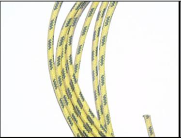
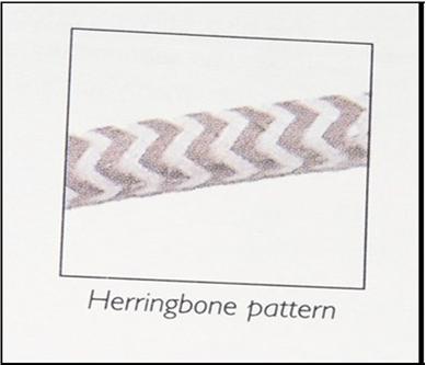
Colour coding of wires consists of two parts, the main colour of the covering and a `tracer` colour,. Iin the period when A7s were built the tracer consisted of a herringbone pattern, later, after 1945, a zig zag or continuous stripe were used. There are seven colours used in the 1935 Lucas standard, Brown, Yellow, White, Green, Blue, Red and Black. The combination of these as a main colour and a tracer gives 33 different combinations.[18 combinations of reproduction cotton covered cable are available from Auto electric Supplies] Each main colour indicates the circuit that the wire is part of :-
Brown: Battery circuit, from the battery or starter motor to the ammeter or the control box, feeds to ignition switch, auxiliary fuse box, horn, radio. Broadly speaking an unfused and
unswitched live feed.
Yellow: Dynamo circuit, from the dynamo output to the cut out or VCU and the ignition warning light.
White: Unfused feed which is live when the ignition is on, eg coil, fuel pump.
Green: Fused feed which is live when the ignition is on eg instruments, brake lights, wipers, indicators.
Blue: Headlamps
Red: Side and tail lamps, panel lamps.
Black: Ground (Earth)
connections.
The tracer colour indicates the specific device that the wire goes to, from August 1934 the wiring diagram shows all these colours. An example of the different feeds is the flashing indicator circuit which would have a green feed, i.e. is protected by a fuse and only works when the ignition is on, the same lamps could also be fed from a hazard flasher which would have a brown feed, i.e. not fused and always available. This leaves restorers of pre 1934 cars with something of a dilemma, to be `period correct` the wiring should all be black and carried in metal conduit but it is much easier for the amateur to trace wiring problems if the wires are colour coded. One solution is to use black cable but to add coloured sleeves which conform to the Lucas standard, at the ends. These sleeves are easily made from `heatshrink` tube and are placed at the end of each wire adjacent to its connection. Do NOT use insulating tape because its adhesive dries out and it falls off!!
Heatshrink markers was the solution I chose when constructing the loom for a saloon race car as, with only 3 reels of cable, the most appropriate wire for the load is always available.
The proper cotton covered cable in all the colour combinations is available from restoration suppliers (at roughly 4 times the price of modern plastic cable) and so any repairs or additions to the system of post 1934 cars can be made without compromising the originality and to the great benefit of future owners! So please throw away all those bits of plastic covered cable that` may come in useful one day` and invest in some proper period cable.
HMP (Devon A7C) with many thanks.