THE AUSTIN 7 THREE SPEED GEARBOX
(Adapted
from an article by Mike Phelan which appeared in the Pre War A7 Club Newsletter
for Sep 93)
There
have been many texts written on the overhaul of the Austin Seven engine,
brakes, steering and most other bits of our favourite car - but the gearbox has
been somewhat left alone. There is, however, good reason for this - it gives
little troub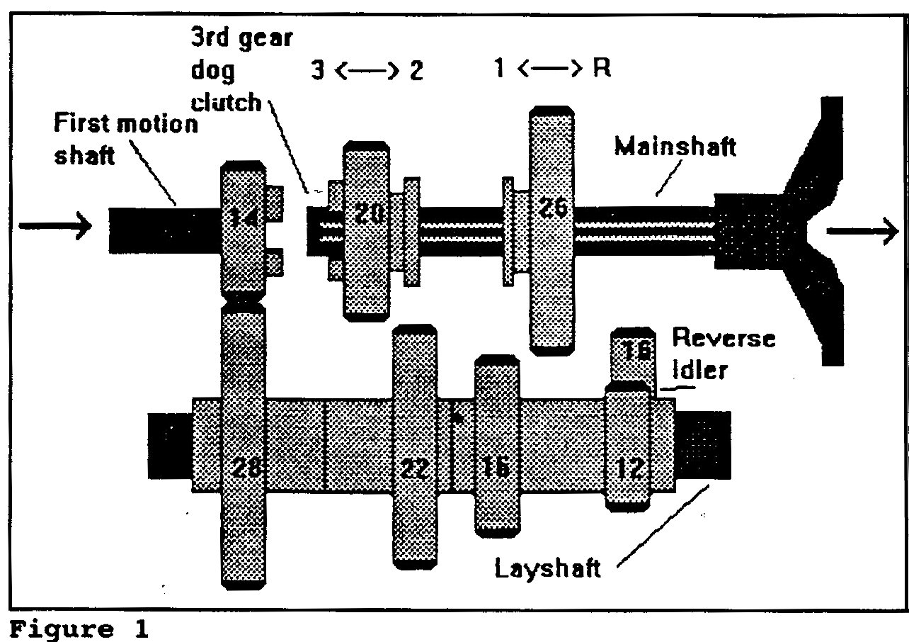 le and continues to give good service, even when absolutely worn
out! Gearboxes rarely fail catastrophically. Nowadays, the supply of good
secondhand gearboxes is slowly diminishing, so we are having to rebuild them,
maybe using parts from several units.
le and continues to give good service, even when absolutely worn
out! Gearboxes rarely fail catastrophically. Nowadays, the supply of good
secondhand gearboxes is slowly diminishing, so we are having to rebuild them,
maybe using parts from several units.
Most
of us will strip an engine with few qualms but steer clear of gearboxes and
differentials, which have fewer parts than an engine! This is perhaps because
of a lack of understanding of how the gearbox works so I make no apologies for
giving a brief elementary description of this: after all, we have a steady
influx of new members to cater for. I crave patience from our more experienced
members.
General Design and Operation: Design
The
unit is a fairly conventional 3-speed sliding mesh gearbox with either a ball
change or a gate change on earlier units. The gate change boxes have a ball
joint at the base of the gear lever, the function of the gate being to restrict
movement and to provide a reverse stop. Ball races are used on the four main
bearings, bronze bushes elsewhere.
Principle of Operation
The
gearbox, like most, has four shafts, viz:
1.
A first motion or input shaft that
is driven by the engine via the clutch. It has an integral constant mesh pinion
to the layshaft (see below).
2.
A mainshaft that delivers output to
the propeller shaft and is locked to the first motion shaft to give top gear,
which therefore has a 1:1 ratio. The mainshaft is splined and carries two
sliding gears.
3.
A layshaft, situated at the bottom
of the gearbox, permanently driven by the first motion shaft. It, in turn,
drives the mainshaft through one of the sliding gears, except when top gear is
selected.
4.
A reverse idler to change the
direction of rotation. This meshes permanently with the reverse pinion on the
layshaft.
The two sliding gears on the mainshaft are moved by selector
forks, and the Seven uses a rather unconventional method of moving these. On
most cars, they are moved by the end of the gear lever. On the Seven, they are
moved by a sliding bar with a hole into which the gear lever end fits. This
gives a slight leverage and a shorter travel on the gear lever. The sliding bar
ends are stepped and fit under two notched bars screwed into the gearbox case
(see Fig 2) 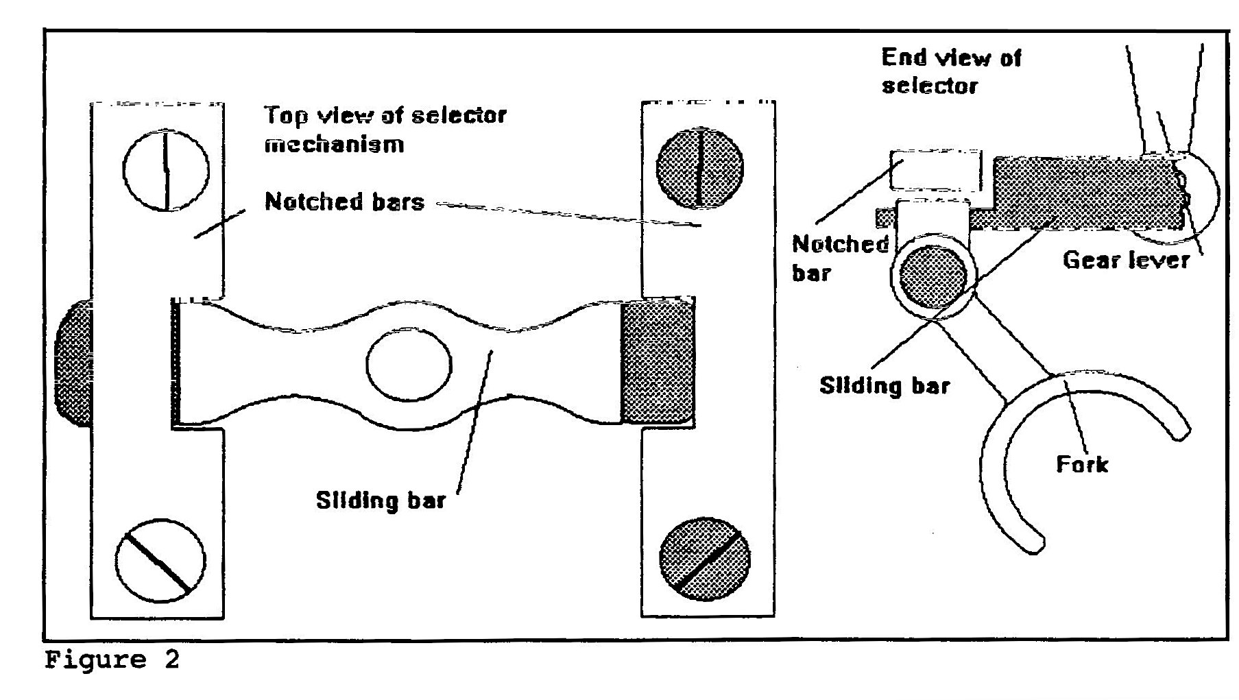 This provides a very necessary part of any selector mechanism, an
interlock to prevent more than one selector fork moving at a time. This, if it
were to happen would lock the box solidly and probably cause sever damage to
the car, and possibly its occupants!
This provides a very necessary part of any selector mechanism, an
interlock to prevent more than one selector fork moving at a time. This, if it
were to happen would lock the box solidly and probably cause sever damage to
the car, and possibly its occupants!
The
interlock operates by having steps on the sliding bar ends that prevent the bar
from moving the forks until it is at the extreme left or right of its travel.
In these positions, one of the stepped ends fits into the notched bar acting as a fulcrum, the other end being clear and free to move. On gate change boxes,
the gate also acts as an interlock.
For
first and reverse gears, the sliding
first gear on the mainshaft is moved into engagement with either the first gear
pinion on the layshaft, or the reverse idler.
For
second gear, the sliding second gear
engages the layshaft second gear pinion.
For
top gear, the face of the sliding
second gear carries four dogs that engage similar dogs on the face of the
constant mesh pinion (see Fig 1), thus locking the mainshaft to the first
motion shaft. The gearbox is now effectively 'out of circuit'.
Gear Changing
When
we are in, say, first gear, doing 15 mph, the engine is rotating at some 3000
rpm and the layshaft at half this speed. If we were doing the same speed in
second gear, the engine would be running much slower and the layshaft rotating
at only 865 rpm. So, therefore, to change upwards silently, we must slow the
layshaft down to somewhere near this speed whilst in neutral so that the two
second gear pinions are rotating in step. As soon as we go from first to
neutral, this starts to happen but the rotating mass of the layshaft, first
motion shaft and clutch driven plate has considerable inertia and would take
some time to reach the required speed. The engine slows down much more rapidly
than this so we briefly release the clutch whilst in neutral to allow the
engine to slow the spinning layshaft.
It
is not quite so simple in practice as there are some variable such as oil
temperature and grade to be taken into account. Cold gearbox oil slows the
shafts down almost immediately but on a hot summer day, upward changes can take
several seconds. Also, if you are on an upward gradient„ the car loses road
speed while you are changing gear so the layshaft slows down even more.
Conversely, road speed increases during a change on a downhill stretch, so that
upward changes can be performed more quickly.
To
change down, the opposite rules apply. The layshaft must be speeded up, so we
rev the engine as we release the clutch in neutral, or just hold the throttle
open moderately. More revs if going down hill, less if going up as the road
speed helps to match the gear speeds.
Gearbox Data
Much
of the data published on gear ratios etc are slightly incorrect. This is rather
surprising as calculating gear ratios simply involves counting the teeth and
performing some very simple arithmetic. Many of the errors have been
perpetuated; as is often the case. William's book on Specials [Ed see A7
Library, Jan 93] gives the ratios for the three speed box to 2 decimal places,
but there are slight errors, even allowing for he axle ratio being stated as
4.9 rather than 4.89 (44/9). I am not trying to be pedantic here, but I think
if figures are stated to an accuracy of 2 decimal places, then they should be
reasonably accurate.
|
Gear
|
Gearbox
|
Overall
|
|
Reverse
|
4.33
|
28/14 X 26/12
|
21.19
|
|
1st
|
3.25
|
28/14 X 26/16
|
15.89
|
|
2nd
|
1.82
|
28/14 X 20/22
|
8.89
|
|
3rd
|
1.00
|
(Direct)
|
4.89
|
As
for the rear axle ratio, we always say 5.25, 5.125 and so on. So why not 4.89
instead of 4.9? The ratios given in 750 MC 'Co
mpanion' are correct. These data
assume a 4.89:1 rear axle ration and a tyre size of 3.50 x 19. This gives 778
turns per mile of the rear wheels. Incidentally, ratios for fourspeed boxes
tend to be mis-quoted sometimes. The early 32/33 crash box has slightly
different (wider) ratios from the later synchro boxes.
|
Engine RPM at various Road Speeds
|
|
MPH
|
1st Gear
|
2nd Gear
|
3rd Gear
|
|
10
|
2060
|
1153
|
|
|
15
|
3090
|
1729
|
|
|
20
|
|
2305
|
1268
|
|
25
|
|
2881
|
1585
|
|
30
|
|
3458
|
1902
|
|
35
|
|
4034
|
2219
|
|
40
|
|
|
2536
|
|
45
|
|
|
2853
|
|
50
|
|
|
3170
|
Close Ratio Conversions
Users
of the 3 speed box will know only to well the wide gap between 1st gear and
2nd. Conversions to reduce this gap have been available for many years. To
convert to close ratio, it is necessary to make a new first motion shaft and
lay shaft constant mesh gear with a reduction ratio less than the standard 2:1
(28/14). If the same pitch of teeth is used, then the total of the teeth on the
two gears must be 421, (the answer to life, the universe and
everything). Say you made new gears of 16 and 26 teeth; this would give you a
first gear of 12.91:1 and a second gear of 7.22:1. As making a first motion
shaft would be extremely expensive, most conversions just machine off the old
gear and press fit a new one.
The sum of the tooth counts for
each of the three pairs of gears must be the same, if the teeth are to have
identical pitch. The three gears used for reverse do not obey this rule as the
reverse idler can be positioned to provide the correct meshing depth.
PROBLEMS
These
gearboxes, as was mentioned last month, are fairly trouble free. Unlike the
later synchromesh boxes, the mainshaft gears do not rotate on the shaft so
there are no bushes to wear. The main problem is noise, due to the rather
course straight-cut gears.
Remember
that even when new, there would have been considerable whine in the indirect
gears. This can be alleviated by using a thicker oil than the recommended
engine oil. I use SAE 50 engine oil in mine, although thicker oils than this
(such as SAE 140) can be used with no apparent damage. If you use your car in
winter, though, using very thick gearbox oil will make changing upward
difficult, for reason mentioned earlier. Avoid oils with sulphur-based
additives, designated 'EP' (extreme pressure) although not all EP oils contain
sulphur. Sulphur
additives will attack any bronze~selector forks and bearings), making your oil
look like gold paint!
Very
severe damage or wear will result in jumping out of gear although this can also
be caused by seized or broken selector springs. The gearbox tops, both types,
wear rather badly as the steel gear lever ball runs directly in the alloy
casting . The ball change top has the lever retained by a threaded ring and the
hole in the top sometimes wears so badly that the lever comes out! The slot in
the ball also wears, but this can be built up by welding. There is definitely a
need for someone to start casting tops of both sorts, or is someone already
doing this?
REMOVAL
Unfortunately,
on all cars with three-speed boxes, the engine will have to be removed, either
with or without the gearbox first. On earlier cars without a dummy spline, it
is easier to lift out the engine separately, then remove the gearbox. If you
remove both together, it will be necessary to remove the cotter from the clutch
pedal to allow the later to rotate clear of the floor, having first removed the
pedal top.
DISMANTLING
Before
doing anything wash the gearbox externally then drain the oil. Collect some old
containers to put small parts in. You will need four small boxes for the
selector shims and a marked piece of wood with four nails for the other shims.
Mark the boxes as shown in the table below:
|
Boxes
|
Board
|
|
1 RF
|
1st/reverse front
|
FM
|
First Motion shaft
|
|
1 RR
|
1st/reverse rear
|
MS
|
Mainshaft .
|
|
23 F
|
2nd/3rd front
|
LSF
|
Layshaft Front
|
|
23 R
|
2nd/3rd rear
|
LSR
|
Layshaft Rear
|
The
first and sometimes the most difficult part to remove is the clutch shaft. This
is retained by two taper pins that must be driven out. If you hit them with a
hammer you will only succeed in flattening them. Use a punch or if that fails,
drill them out. Be very careful of the brittle gearbox casing. Remove the
clutch shaft and withdrawal levers, noting the position of the washers. Then
remove the gearbox top and front covers and put to one side.
Warm
the gearbox casing with a fan heater, or use a hot-air gun but be very careful.
This makes removing the bearings much easier. When taking the front cover off,
turn the box front uppermost, so that the our sets of shims do not fall out.
These must be put in the marked containers unless you want to start from
scratch when re-assembling. Granted, we are assuming that the box has not been
stripped before - true in a surprising number of cases. Some shims may be stuck
to the cover. There are large shims on the two ball races and small ones about
the size of a 5p piece, on the selector rails. The latter may remain in the end
of the bore. The layshaft rear bearing has a pressed steel disk on top of the
'N shims. This is a distance piece and care must be taken during reassembly not
to replace it in the front bearing in error. Take out the four screws holding
the notch bars; you may need an impact driver for this. The selector bars will
then be free and can be removed.
Take
out the speedo drive bush and pinion if present. Remove the rear cover,
complete with mainshaft which will slide out. Again beware of shims - four lots
again!
The
selectors can be removed, but carefully! Push each rail rearwards and continue
until it is flush with the end of the selector fork. Then put your thumb and
finger over the fork end and the small hole in the top and pull the rail out.
The steel ball will now be loose inside the fork and can be retrieved, possibly
with aid of a magnet. Repeat the process with the other fork. As the rods are
identical, mark then so they can go back in the same positions. The springs can
be pulled out with a wire hook.
The
two sliding gears can be taken out now and a brass drift used to remove the
first motion shaft. The layshaft is a little more difficult. The gear is in
three parts, retained by two keys which will not pass through the bearings. To
remove, tap the shaft rearwards until the rear bearing is free of the case.
Turn the box on its front and place two pieces of brass or alloy strip between
the bearing and case. Drift the layshaft back into the box and remove the
bearing. Continue to drift the shaft out forwards, retrieving the two keys. The
longer one is invariably broken in two pieces. The reverse idler shaft can now
also be drifted out.
Remove
the circlip from the mainshaft, remove the shaft, bearing and seal plus the
speedo drive worm if fitted.
Examination
Wash
all parts off in a degreasing fluid or paraffin followed by petrol. Examine
the gear teeth for corrosion or pitting that has penetrated the case hardening.
The engaging edges of the gears should be chamfered, but look for damage and
chipping which will cause noise and jumping out of gear.
The
layshaft is frequently bent but replacements are inexpensive. The keys will
need replacing, too, but the long one probably breaks in the first 1000 miles!
Bearings do not wear much, replacing them may increase noise by changing the
depth of engagement. Give the four ball races a final wash in clean petrol and
check them for wear and roughness. If you are going to re-use them, oil them
with engine oil and wrap in paper to keep the dust out until you re-install
them. Any felt seals will need replacing with new ones soaked in molten tallow.
The spigot bearing in the First Motion Shaft sometimes wears slightly.
The
selector forks tend to wear where the sliding bar engages them. Building these
up with bronze will improve the change considerably. The notched bars can also
wear, and can be built up with weld. Do not, however, give the final finish
until the box is being re-assembled, as they need to be fitted exactly.
When
replacing gears with those from another box, replace them in pairs if possible,
or you may end up with a noisy box. Remember to include the reverse idler, and
that it rotates all the time that the clutch is engaged. A severely worn idler
can produce a surprising amount of noise, even in neutral. Ensure that all the
ball races are tight, on the shaft and in the case. Clear out the spring holes
in the selector forks with a drill or reamer, as they tend to burr. Throw the
old selector springs away.
Reassembly with Original Shims
If
you are not replacing all the shims in their original positions, refer to the
next section for details of how to set up the gearbox by re-shimming and this
section for detailed assembly instructions.
The
first thing to do is to place all the layshaft gears in the bottom of the box, then
to feed the layshaft from the front, not forgetting to fit all the keys, which
can be stuck in place with grease. The long key goes to the front. It sometimes
helps if the first 1/8" or so of the keyways in the gears is chamfered
with a needle file. This avoids the sharp edge planing a shaving off the key.
When the layshaft is fully in position, fit both bearings after warming the
casing up again. Use a tubular drift, with a block of soft metal supporting the
other end of the shaft. An extra pair of hands is useful here. Tap the rear
bearing in the furthest, to allow room for the distance piece.
Replace
the first-motion shaft and bearing, and temporarily fit the mainshaft into the
two sliding gears. Place both selector forks in position, noting the markings
that you made on dismantling. The selector shafts will then need fitting, and
this is a slightly awkward job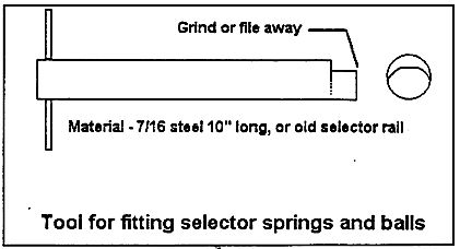 , due to the fact that the springs need
compressing.
, due to the fact that the springs need
compressing.
I
find that the best way to do this is to make up a special tool consisting of a
piece of bar as in the drawing opposite. To
use it, put the spring and ball, heavily greased, into position and insert the
tool into the front of the fork bore until the end just covers the hole. Turn
the tool a quarter turn; this will compress the spring. Fit
the shafts into position as follows. The 2"d/3' shaft is the one with the
grooves unequally spaced. Look for the wear
on the grooves caused by the ball and fit the shaft so this wear is at the top.
Push the shaft in till it
meets the tool, then give a tap with a hide mallet or soft drift whilst holding
the tool. Once the shaft has
gone in past the hole, remove the tool and tap the shaft home until 1/8"
or so short of the front face
of the gearbox.
Turn
the gearbox front uppermost and fit all the original shims in position, then
the gasket and the front cover. Turn it over, remove the mainshaft and assemble
the latter with seal, bearing and speedo worm to the rear cover. Refit the
circlip and close with a vice. Tap the selector rails forward and do the same
to the layshaft bearing. This ensures that there is no looseness in the shims
at the front. Refit the rear shims, the distance piece on the layshaft and the
gasket. Refit the rear cover and tighten the bolts.
Reassembly with New Shims
In
an ideal world, if we replace all the shims in the positions that they came
from, all will be well. Unfortunately, if the box has been stripped before, or
any parts swapped, it will be necessary to re-shim the box. To do this, you
really need a selection of shims as well as those fitted originally, but it may
be possible to just use the original shims. The process must be carried out in
the correct order, as most of the shims affect more than one thing. Like any
similar process, the aim is to finish with the adjustment that only affects one
item.
What
are we aiming for? Full
engagement of the reverse idler and the layshaft reverse pinion. Full
engagement of 1S`, reverse and 2"d gears, and equal clearance in neutral.
Correct engagement of 3rd gear dog clutch.
Full engagement of the constant mesh
pair.
Procedure:
The box is assembled as in the previous section, except that the covers are
left off the mainshaft and the first motion shaft, and the balls and springs
are left out of the selectors. This is so that the gears can be engaged without
disturbing the positions of the selector rails. Ensure that the layshaft is
likewise pressed hard against the ends of the gear cluster and that the first
motion shaft bearing is likewise fully home. Check that the selector rails are
a firm fit in the gearbox case and cannot move easily.
1. Put the 1st/reverse selector in the reverse gear position
(back) and pop the ball, with some grease on it, into the top hole to
centralise it.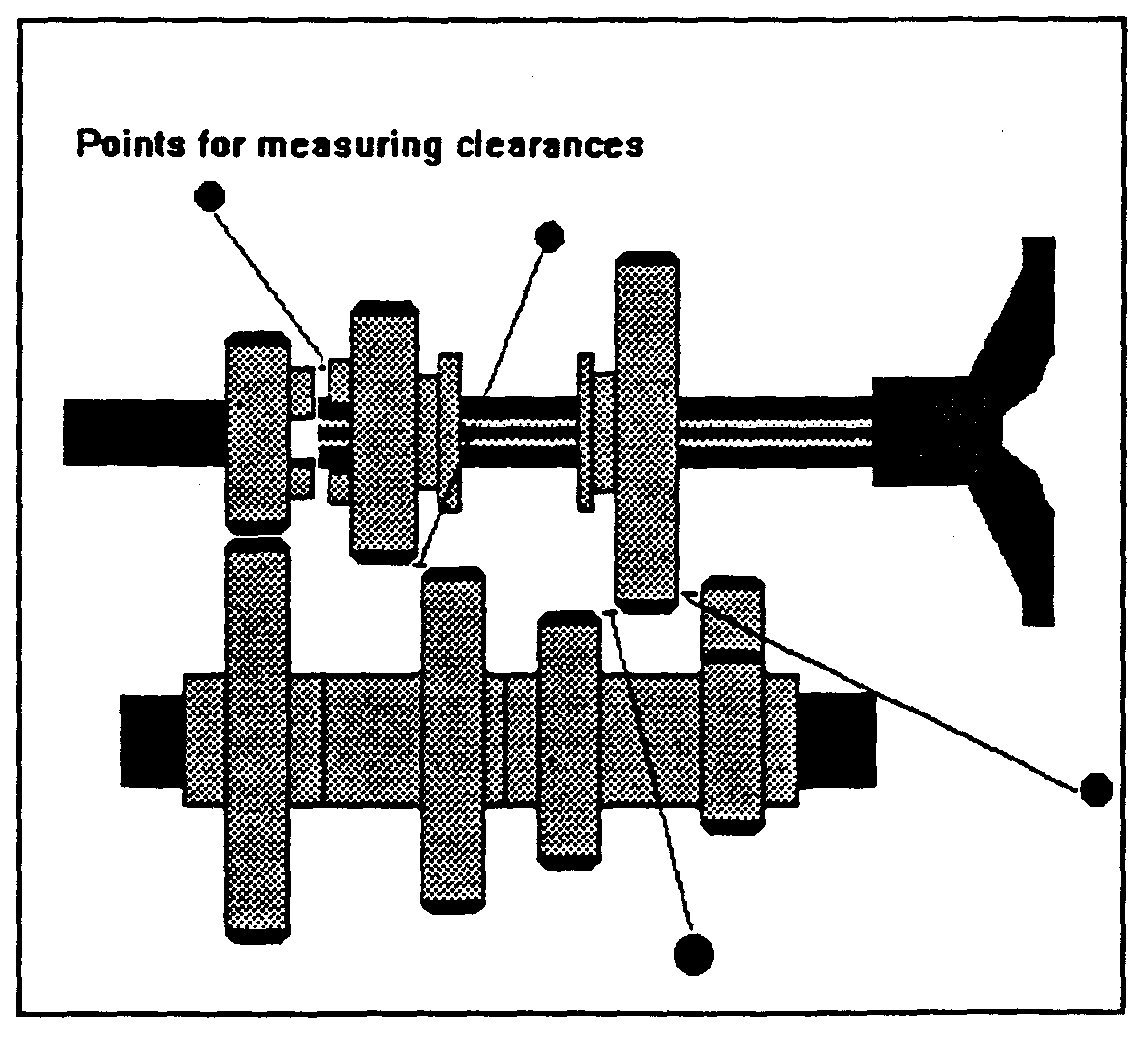
2. Tap the selector rail either way, holding the ball in place,
until the sliding gear and reverse idler appear to be fully engaged.
3. Tap the layshaft bearing (not the shaft) with a hollow drift
until the reverse pinion on the layshaft engages fully with the idler.
4. Return the selector to neutral and check that the clearances
either side of the 1st/reverse sliding gear are equal and at least 0.1".
If it is too near the layshaft first gear, move the layshaft; if to near the
reverse idler, move the selector rail.
5. Repeat adjustments 2, 3, and 4 until correct.
6. Place the 2"d/3' selector in neutral and stick a ball
in the top hole with grease, as before.
7. Tap the first motion shaft bearing outer race, not the
shaft, until the constant mesh gears engage correctly and there is at least
0.1" clearance between the halves of the dog clutch.
8. Tap the selector rail to give 0.1" clearance between
the sliding second gear and the corresponding layshaft pinion.
9. Repeat 6, 7 and 8 until correct.
10. With a straight edge and feeler gauges, measure the depth of
the two front ball races below the gearbox face and write these down. Do the
same with selector rails (front only).
11. Remove the selector rails and refit the
balls and springs (see previous section).
12. Fit a new seal to the front cover and fit
the washer that retains it.
13. Select shims to the thickness that you noted, plus the
thickness of the front cover gasket, and support the box front upwards. Fit the
four sets of shims and the gasket, coated in goop if you wish, then bolt down
carefully.
14. Tap the mainshaft gently until it will move no further. Also
tap the layshaft rear bearing and the selector rails, the latter only gently.
15. Measure the depths as you did the front.
Add the thickness of the gasket to the figures and from the mainshaft bearing
depth, deduct 0,020" for spigot bearing end float. From the layshaft
figure, deduct the thickness of the distance piece.
Remove
the mainshaft and bearing, refit the cover with a new seal and washer. Squeeze
the circlip into its groove in a vice - it is very soft, fit the shims and
gasket and replace the cover. This completes the shimming process.
Reassembling the Selector Bars
Place
both selector forks in neutral, then refit the sliding bar, well greased. The
notched bars should then fit so that the sliding bar slides freely, with equal
clearance either side of the square portions where they enter the notches. Try
swapping the bars around for the best fit. If the latter have been built up
with weld, the notches can be filed for an exact fit. Clearance should be no
more than necessary to allow free movement.
Replace
the screws using an impact driver and punch metal into the slots to lock them,
as they were before. Check finally that all gears can be engaged after fitting
the top temporarily.
Refitting the Gearbox to the Car
This
should be self-explanatory. If the clutch pedal has been removed, make sure the
cotter is refitted from the rear. Cotters of this type have a slope of some 10°
so fitting the cotter the wrong way round will mean the loss of some 20° of
clutch pedal movement - on a Seven this is an extravagance! Note this also when
replacing other cotters, particularly those in brake cam levers.
Lubricate
the clutch release bearing with castor oil. This tip was given to me by someone
who worked on Sevens during the Twenties and Thirties and seems to work well.
The bearing seems to last forever on a three-speed but the four-speed bearings
(that do not rotate continuously) are generally noisier.
If
you are fitting the gearbox, then the engine, there are two. points to watch:
First,
turn the engine and feel that each toggle lever is in its slot in the release
ring before bringing the engine and gearbox finally together.
Second,
fit the nuts on the bell housing before sliding the engine back into position,
as two of them are pretty well inaccessible afterwards.
The
job is easier if the gearbox top is fitted and the gearlever can then be used
to manoeuvre the box into position. Do not forget the oil!
(Adapted
from an article by Mike Phelan which appeared in the Pre War A7 Club Newsletter
for Oct 93 with many thanks)